
Brake fluid pressure control unit

a technology of pressure control unit and brake fluid, which is applied in the direction of brake system, brake components, vehicle components, etc., can solve the problems of difficulty in standardizing processes, hydraulic pressure on the upstream side (on the master cylinder side) of pressure increase valves and pressure reduction valves cannot be detected by the pressure sensor, etc., to achieve the effect of improving productivity, increasing internal channels, and reducing costs

Active Publication Date: 2017-01-31
ADVICS CO LTD
View PDF22 Cites 0 Cited by
  • Summary
  • Abstract
  • Description
  • Claims
  • Application Information

AI Technical Summary

Benefits of technology

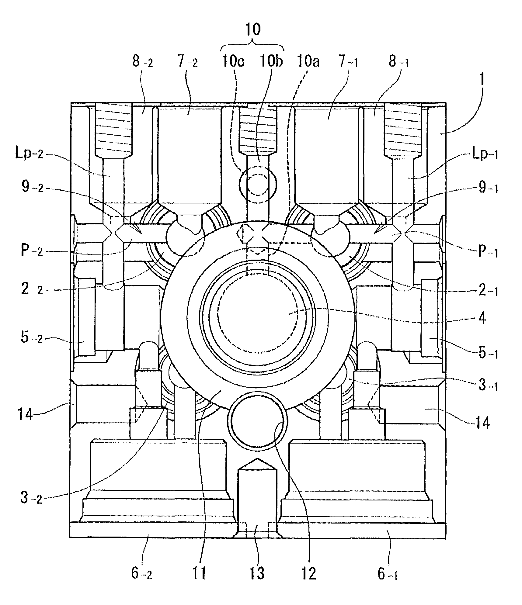
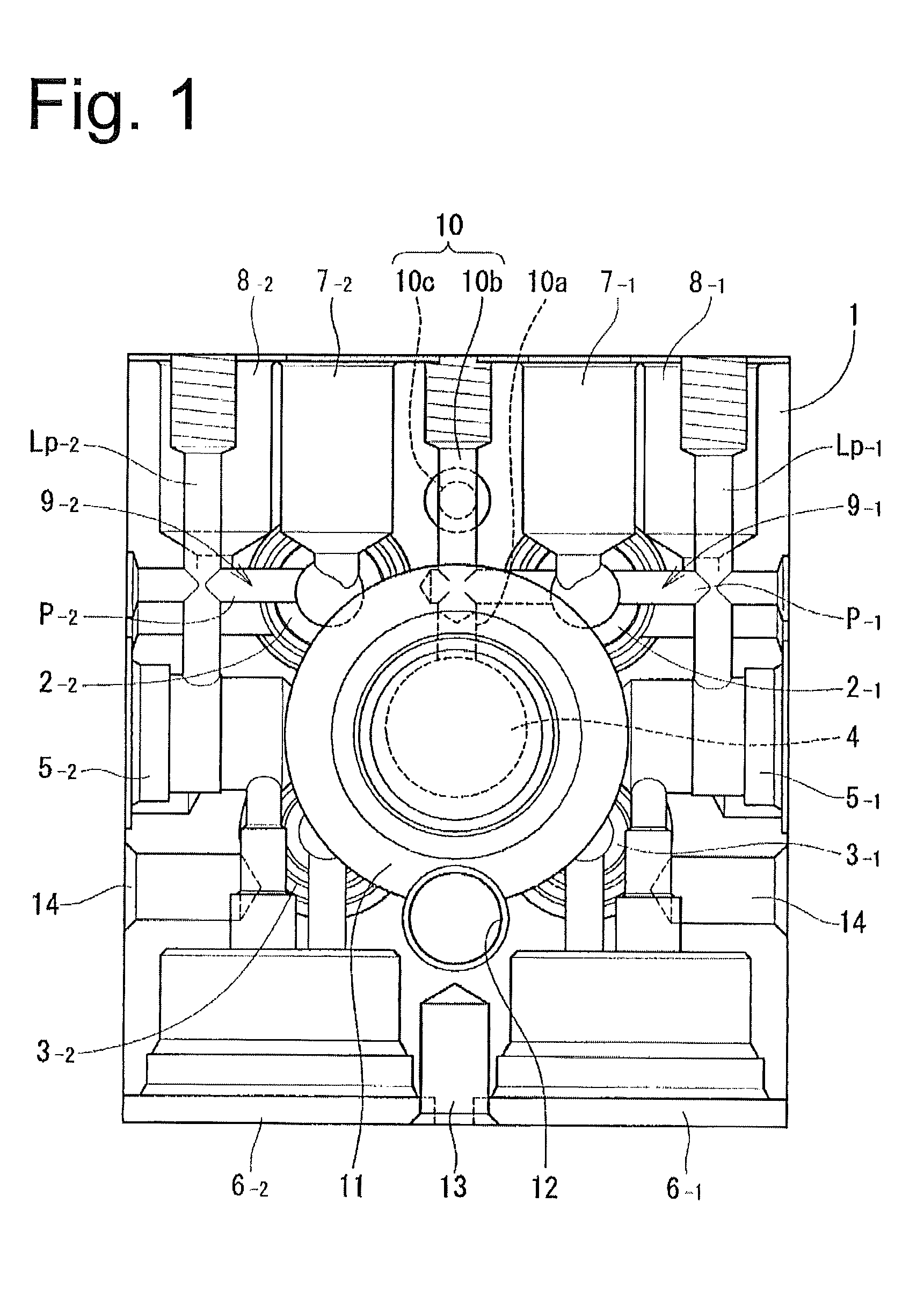
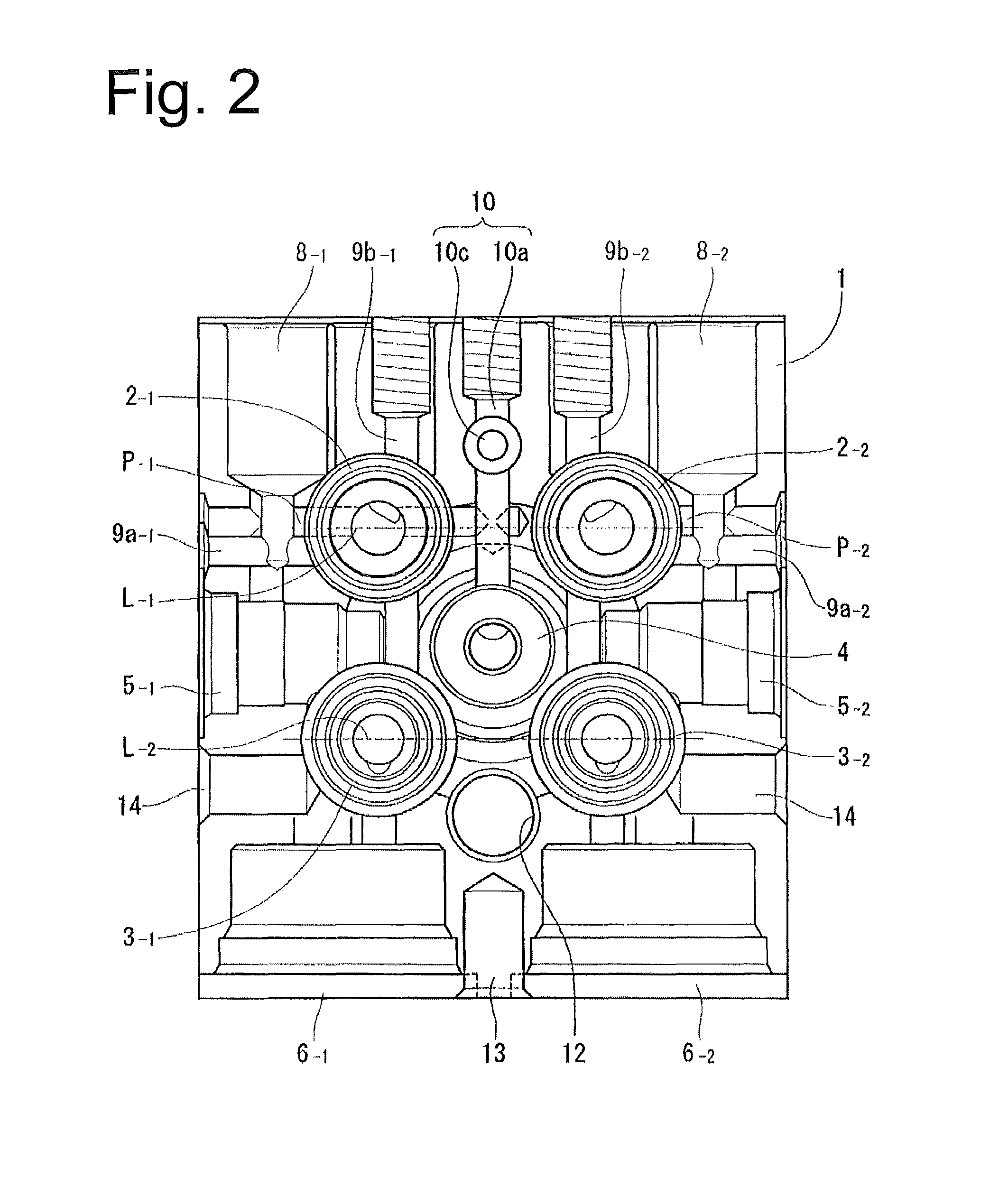
[0021]In the brake fluid pressure control unit according to the invention, the internal channel for the first system and the internal channel for the second system provided in the housing of the hydraulic block can be selectively connected to the same pressure sensor by machining to increase the depths of the internal channels. Therefore, in terms of detecting pressures at the total of four points, which are the respective upstream points and downstream points of the pressure increase valve in the system, the housings for the corresponding hydraulic blocks can be standardized at the stage of processing. For example, it is possible to standardize the housings into one type.
[0022]In the standardized housing, requirements for the specifications of the different detecting points can be satisfied. Accordingly, it is possible to standardize the housings and hence processes, thus improving productivity and reducing costs.
[0023]The detected hydraulic pressure inlet hole is disposed so as to meet either one the first or second holes composing the internal channels for the first and second systems respectively and also disposed on the line extending from the other. Thereby, hydraulic pressure can be detected in only one of the first and second holes. Selecting the first or second hole to meet the detected hydraulic pressure inlet hole makes it possible to change a detection point for hydraulic pressure.
[0024]In this structure, the first hole and the second hole can be provided opposite each other, thus increasing use efficiency of the arrangement of space in the housing and reducing the size of the housing.
[0025]Additionally, in the configuration in which the first hole and the second hole are provided opposite each other and the detecting hydraulic pressure inlet hole is disposed vertically across the first and second holes, the first and second holes and the detected hydraulic pressure inlet hole can be located in different positions vertically, which makes it possible to increase freedom in the layout of the internal channels, facilitating a further reduction in size of the housing.
[0026]In the configuration in which the first hole and the second hole are composed of the corresponding holes connecting the corresponding pressurizing ports and the respective discharging ports of the corresponding pumps or the configuration in which the first hole and the second hole are composed of the corresponding holes connecting the following three, i.e., the corresponding pressure increase valves, the corresponding pressure reduction valves, and the corresponding wheel cylinder ports, the pressure sensor can be connected to the detection points by using holes located as parts of the corresponding internal channels for the first and second systems. Accordingly, machining and space for arrangement can be reduced, compared to the form in which dedicated holes are newly provided.

Problems solved by technology

Therefore, the pressure sensor accommodating hole cannot be connected to a master cylinder connection hole formed in the upper part of the housing (i.e., the motor terminal hole blocks the formation of a communication hole).
As a result, the hydraulic pressure on the upstream side (on the master cylinder side) from the pressure increase valves and pressure reduction valves cannot be detected by the pressure sensor.
Where hydraulic blocks are independently designed for these setting aspects, the housings to be controlled increase, making it difficult to standardize processes, with the result that adverse effects may be exerted on productivity and cost.
The structure in the Patent Document 1 cannot cope with this problem.

Method used


Image

  • Brake fluid pressure control unit
  • Brake fluid pressure control unit
  • Brake fluid pressure control unit

Examples


Embodiment Construction

[0043]An embodiment of a brake fluid pressure control unit according to the present invention will be described below with reference to FIGS. 1 to 13 in the attached drawings. FIG. 13 shows an example of a brake fluid pressure control unit for a two-wheeled vehicle. This brake fluid pressure control unit 20 includes pressurizing sources 22_1, 21_2 (i.e., master cylinders in FIG. 13) activated by operating the left and right brake levers 21_1, 21_2 of the two-wheeled vehicle. These pressurizing sources 22_1, 22_2 are able to produce hydraulic pressures independently by individually operating the brake levers 21_1, 21_2 in the same order as above.

[0044]Additionally, the brake fluid pressure control unit 20 includes: hydraulic passages 24_1, 24_2 for first and second hydraulic systems, respectively, reaching to the wheel cylinders 23_1, 23_2, respectively; pumps (piston pumps or gear pumps) 25_1, 25_2 installed in the first and second hydraulic systems respectively; a motor 26 that dri...


PUM


Abstract

A brake fluid pressure control unit for a vehicle comprises: a hydraulic block that includes a housing containing an internal channel for a first system and an internal channel for a second system, which individually allow communication with a wheel cylinder for a first wheel and a wheel cylinder for a second wheel respectively, and also containing a detected hydraulic pressure inlet hole leading to a pressure receiving part of a pressure sensor. A first hole included in the internal channel for the first system and a second hole included in the internal channel for the second system can selectively be connected to the detected hydraulic pressure inlet hole by machining such that the depth of either the first hole or the second hole is made greater than the other.

Description

TECHNICAL FIELD[0001]The present invention relates to a brake fluid pressure control unit for a vehicle, which is designed such that a hydraulic block (housing) incorporating pressure regulating elements for brake fluid is standardized at the stage of processing (i.e., products before finishing process).BACKGROUND ART[0002]A brake fluid pressure control unit for a vehicle is configured by combining: a hydraulic block incorporating a pump for power drive, pressure increase valves and pressure reduction valves, a pressure sensor, and a reservoir used for taking in brake fluid discharged via the pressure reduction valve from wheel cylinders (wheel brakes) and for supplying it to the pump; an electronic device equipped with an ECU (Electronic Control Unit) that controls driving a motor, the pressure increase valves, and the pressure reduction valves; and the motor that drives the pump. A known example for the brake fluid pressure control unit is disclosed in, for example, the Patent Doc...

Claims


Application Information

Patent Timeline
Patent Type & Authority Patents(United States)
IPC IPC(8): B60T8/34B60T8/32B60T15/02B60T8/36
CPCB60T8/346B60T8/3225B60T8/368B60T15/028
Inventor OTAKE, TSUYOSHI
Owner ADVICS CO LTD
Learn More