Fabric structure with cellular construction

a technology of cellular construction and fabric structure, which is applied in the direction of open work fabrics, ornamental textile articles, textiles and paper, etc., can solve the problems of not being self-supporting or stable against axial displacement, the production of metal foam is very time-consuming and cost-intensive, and the method is also labor-intensiv

Active Publication Date: 2017-02-07
DRESDEN UNIVERSITY OF TECHNOLOGY
View PDF26 Cites 0 Cited by
  • Summary
  • Abstract
  • Description
  • Claims
  • Application Information

AI Technical Summary

Benefits of technology

[0027]Preferably the take-down takes place linearly without stress of the fabric structure or application of superposed rollers. Other forms of the take-down are also possible, where the fabric structure in z-direction is not irreversibly deformed, such as for example through application of needle rollers that are distanced relative to each other.

Problems solved by technology

The production of metal foams is very time consuming and cost-intensive.
These structures are however neither self-supporting nor stable against axial displacement but must be kept in a defined position and fixed by gluing, soldering or welding.
This method is also very labor intensive and due to complex requirements not yet fully automated.
The structures known from the prior art are partly not self-supporting and not form-stable; that is, the single layers of the structures are partly axially displaceable against each other.
None of the known structures can be produced fully automated, respectively, the production requires multi-step processes.
An efficient commercial production can thus not be realized.

Method used


Image

  • Fabric structure with cellular construction
  • Fabric structure with cellular construction
  • Fabric structure with cellular construction

Examples


Embodiment Construction

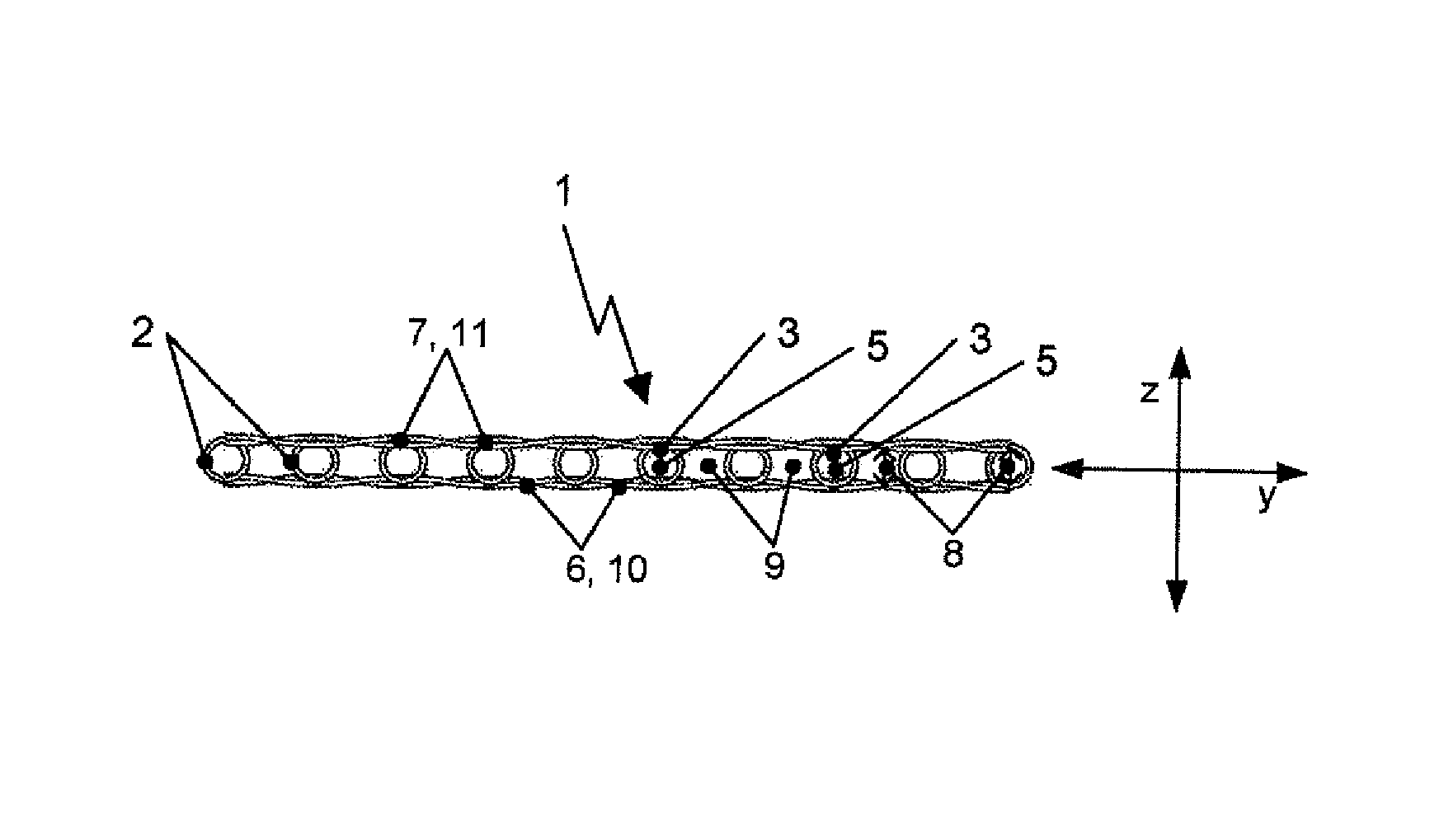
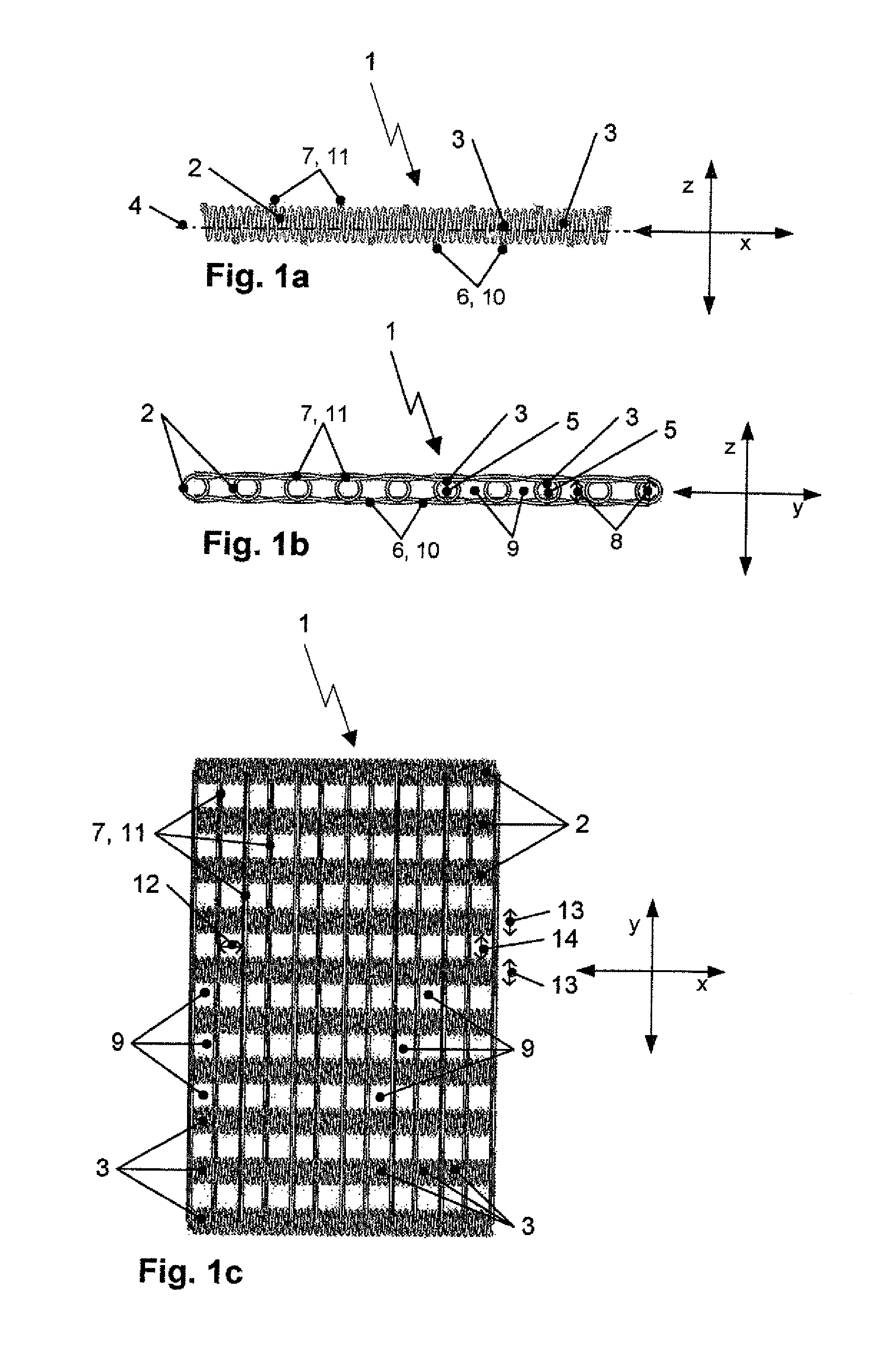
[0037]The drawings in FIGS. 1a to 1d represent only one of the possible arrangements for the reinforcement material. FIG. 1a shows a side view of a schematically illustrated fabric structure 1 along the weft direction x. The weft thread 2 is a so-called spiral wire 2. As FIG. 1a shows in combination with the side view of FIG. 1b along the warp direction y, this weft thread extends three-dimensional form-stable and winds itself along the weft direction x around an axis 4 extending in weft direction x and through each row of cells 3. Thereby, the weft thread 2 encloses around this axis 4 an imaginary three-dimensional elongated hollow body with a circular-shaped end face 5 around which the form-stable, three-dimensional weft thread winds in a spiral manner in the weft direction x.

[0038]In addition, FIGS. 1a and 1b show in the side views of the fabric structure 1 in weft direction x and in warp direction y, a base layer 6 and a cover layer 7 between which several form-stable spiral-sha...


PUM

PropertyMeasurementUnit
heightaaaaaaaaaa
lengthaaaaaaaaaa
widthaaaaaaaaaa

Abstract

A fabric structure (1) having a cellular construction. The fabric structure comprises at least one base layer (6) consisting of warp threads (10), at least one top layer (7) consisting of warp threads (11) and weft threads (2) placed in between, wherein the fabric structure (1) is formed by a multiplicity of three-dimensional cells (3, 9) and the height (8) of each individual cell (3, 9) is defined by the spacing (8) between two warp threads (10, 11), located above the other in height direction z, in adjacent layers (6, 7), the length (12) of the cell (3, 9) is defined by the spacing (12) between two warp threads (10) or (11) adjacent in the weft direction x, in one layer (6, 7) and the width (13, 14) of a cell (3, 9) is defined by the extent (13) of the weft thread course in the warp direction y and/or the spacing (14) between the two weft threads (2) that are opposite in the warp direction y and adjacent to the particular cell (9). According to the invention, each weft thread (2) extends at least regionally in the fabric structure (1) in a dimensionally stable and three-dimensional manner and winds in the weft direction x about this axis (4) an imaginary, three-dimensional elongate hollow body, extending through the cells (3), having any desired end face (5). The weft threads (2) intersect the warp threads (10, 11) such that the weft threads (2) and warp threads (10, 11) retain one another and the fabric structure (1) is self-supporting.

Description

CROSS-REFERENCES TO RELATED APPLICATIONS[0001]This application is the U.S. National Stage of International Application No. PCT / DE2014 / 100041, filed Feb. 6, 2014, which designated the United States and has been published as International Publication No. WO 2014 / 121787 and which claims the priority of German Patent Application, Serial No. 10 2013 101 219.1, filed Feb. 7, 2013, pursuant to 35 U.S.C. 119(a)-(d) the description of which is hereby incorporated by reference.BACKGROUND OF THE INVENTION[0002]The present invention refers to a fabric structure having cellular construction. This fabric structure is for example for use in light weight construction.[0003]Typical cellular metallic light weight structures are metal foams. The production of metal foams is very time consuming and cost-intensive. There are light weight structures from lattice-shaped and honeycombed constructed polymer material. Lately, there is research activity on three-dimensional wire structures. Thus, at the Chonn...

Claims


Application Information

Patent Timeline
Patent Type & Authority Patents(United States)
IPC IPC(8): D03D11/00D03D15/02D03D9/00D03D25/00D03D15/00
CPCD03D25/005D03D9/00D03D11/00D03D15/0083D03D15/02D10B2101/20D10B2403/021D03D15/44D03D15/593D03D15/37D03D15/67
Inventor SENNEWALD, CORNELIAHOFFMANN, GERALDCHERIF, CHOKRI
Owner DRESDEN UNIVERSITY OF TECHNOLOGY
Why Eureka
Try Eureka