an automatic locking device

An automatic locking and locking block technology, applied in the direction of quick-acting fasteners, rigid shaft couplings, mechanical equipment, etc., can solve the problem of inability to install and remove, and achieve the effect of convenient manufacturing, easy installation and use

Active Publication Date: 2015-09-09
WANXIANG QIANCHAO TRANSMISSION SHAFT +1
View PDF3 Cites 0 Cited by
  • Summary
  • Abstract
  • Description
  • Claims
  • Application Information

AI Technical Summary

Problems solved by technology

[0003] The purpose of the present invention is to overcome the deficiencies of the prior art, and provide an automatic locking device that solves all the problems that cannot be loaded and unloaded due to space constraints, and is very easy to load and unload, and has strong reliability.

Method used


Image

  • an automatic locking device
  • an automatic locking device
  • an automatic locking device

Examples


Embodiment Construction

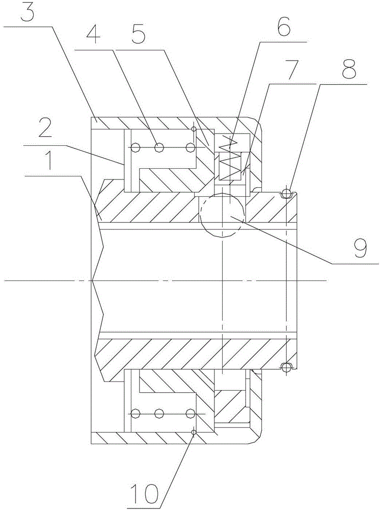
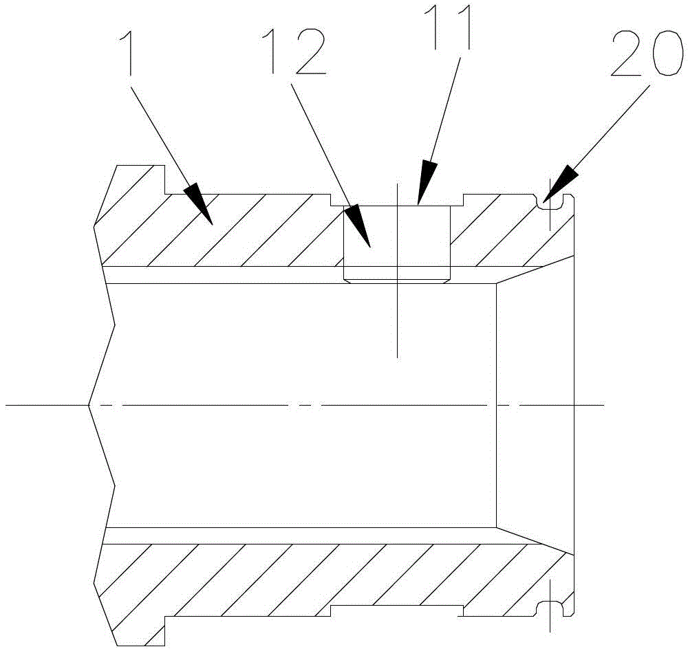
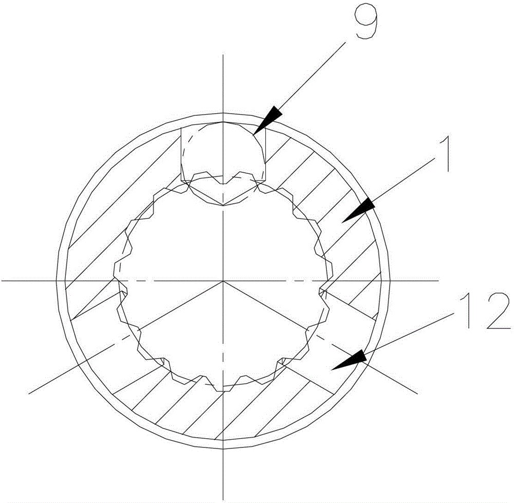
[0014] The present invention will be described in detail below in conjunction with accompanying drawing: figure 1 , 2 , 3, and 4, the present invention includes a spline connection fork 1, a sliding ring 3, and a steel ball locking block 5. The outer diameter of the spline connection fork 1 is provided with a draw-in groove 11, and the draw-in groove 11 The eccentric ring 7 is stuck; the steel ball locking block 5 is set on the spline connection fork 1, and is close to one side of the eccentric ring 7; the steel ball locking block 5 and the stop ring 2 are sandwiched The large spring 4 and the stop ring 2 are limited to the stepped groove of the splined connection fork 1, the stop ring 2 and the steel ball locking block 5 are located in the sliding ring 3, and the sliding ring 3 is sleeved on the splined connection fork 1.

[0015] The eccentric ring 7 is provided with an inner groove 71 , and the small spring 6 against the sliding ring 3 is placed in the inner groove 71 . T...


PUM


Abstract

The invention relates to an automatic locking device which comprises a spline connection fork, a sliding ring and a steel ball locking block. A clamping groove is formed in the external circle of the spline connection fork. An eccentric ring is clamped in the clamping groove. The steel ball locking block is sleeved on the spline connection fork and is close to one side of the eccentric ring. A big spring is clamped between the steel ball locking block and a check ring. The check ring is limited on a step groove in the spline connection fork. The check ring and the steel ball locking block are located in the sliding ring. The sliding ring is sleeved on the spline connection fork. The automatic locking device has the advantages that due to the fact that the automatic locking device is of an integral structure, manufacturing is convenient and fast and convenient usage and installation are achieved; due to the fact that general materials are designed to achieve complex motions, the whole structure is enabled to be stable by means of the specificity of the materials, and safety and attractive appearance are achieved for a transmission shaft which needs a high-speed rotary part.

Description

technical field [0001] The invention relates to a locking device, mainly an automatic locking device which can be designed according to the size of the transmission shaft. Background technique [0002] With the rapid development of industrial and agricultural machinery automation, it is essential for mechanical equipment to achieve multi-drive and multi-action. The transmission shafts used for power transmission drive are more extensive, and there are higher requirements for transmission shafts. Then the traditional bolts, keys, splines, pins, etc. are connected, which need to meet the needs of the whole machine layout. If the drive shaft is installed in a specific space to transmit the driving force, the spline connection cannot be fixed with bolts and pins. It is even more impossible to load and unload with the traditional method. Contents of the invention [0003] The purpose of the present invention is to overcome the deficiencies in the prior art, and provide an auto...

Claims


Application Information

Patent Timeline
Patent Type & Authority Patents(China)
IPC IPC(8): F16D1/10F16B21/07
CPCF16D2001/103F16D1/108
Inventor 祝贡校陈惠峰张平朱柏贤
Owner WANXIANG QIANCHAO TRANSMISSION SHAFT
Why Eureka
Try Eureka