Hip resurfacing

a hip and hip technology, applied in the field of hip resurfacing, can solve the problems of femoral head-neck relationship that is difficult to quantify, early loosening, and accelerated wear, and achieve the effect of accurate positioning of the acetabular cup in the pelvis, without the risk of impingement, and reliable method

Active Publication Date: 2017-02-14
IMPERIAL INNOVATIONS LTD
View PDF20 Cites 0 Cited by
  • Summary
  • Abstract
  • Description
  • Claims
  • Application Information

AI Technical Summary

Benefits of technology

[0020]Some embodiments of the invention can therefore provide any one or more of the following:a method for orienting an acetabular implant in the relation to the pelvis specific for pelvic morphology and gender;a method for locating the acetabular cup in relation to the pelvis specific for pelvic morphology and gender;a shape of acetabular cup that both minimizes soft tissue damage from overhanging metal edges in the socket and maximizes femoral head coverage and pelvic bone support;a shape of acetabular cup that optimizes load transfer, to minimize wear;a shape of acetabular cup that has an ilio-pubic recess for the psoas tendon of a shape and position defined by the algorithm;a shape of acetabular cup that includes an ischial ‘facet’ to increase surface area and enhance stability in flexion;a method for orienting the femoral head implant in relation to the femur specific for femoral morphology and gender;a method for locating the femoral head implant in relation to the femur specific for femoral morphology and gender;a shape of femoral component that minimizes soft tissue and blood vessel damage to the underlying femoral head and adjacent femoral neck posterosuperiorly;a shape of femoral head implant that minimizes the risk of fracture of the femoral neck due to notching anterosuperiorly in cam type hip deformity;a shape of femoral head implant that has an extended flexion and extension facet;an internal shape that can accommodate the relative anterosuperior deficiency in cam type hip deformity by having an internal cavity that is partially filled-in so as to effectively substitute for that portion of the bone that is missing.
[0021]The present invention provides a novel anatomic design of the acetabular cup. A reliable method for accurately positioning the acetabular cup in the pelvis is also provided. The present invention can help to provide an optimally placed anatomic hip device providing an optimum range of motion without the risk of impingement and associated with low wear rates.

Problems solved by technology

It has been shown that acetabular cups that overhang the rim of the acetabulum are associated with impingement, early loosening and accelerated wear.
Determination of the 3D position of the acetabulum in the pelvis and the femoral head in relation to the femoral neck has continued to be a challenge.
Femoral head-neck relationship is similarly difficult to quantify.

Method used


Image

  • Hip resurfacing
  • Hip resurfacing
  • Hip resurfacing

Examples


Embodiment Construction

[0067]Acetabulum

[0068]CT scans of 22 normal acetabula were analysed using 3D reconstruction software. These included 12 dry cadaveric innominate bones containing normal acetabula. In addition post-operative CT scans from 12 patients with unilateral acetabular fractures were used to analyse the normal contralateral acetabulum. The mean age of these patients was 38.4 years (range 22-61 years). There were five females and seven males. The gender of the cadaveric bones was not known.

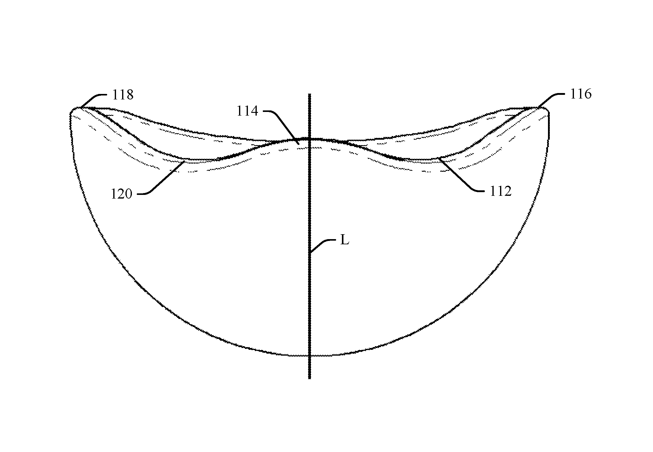
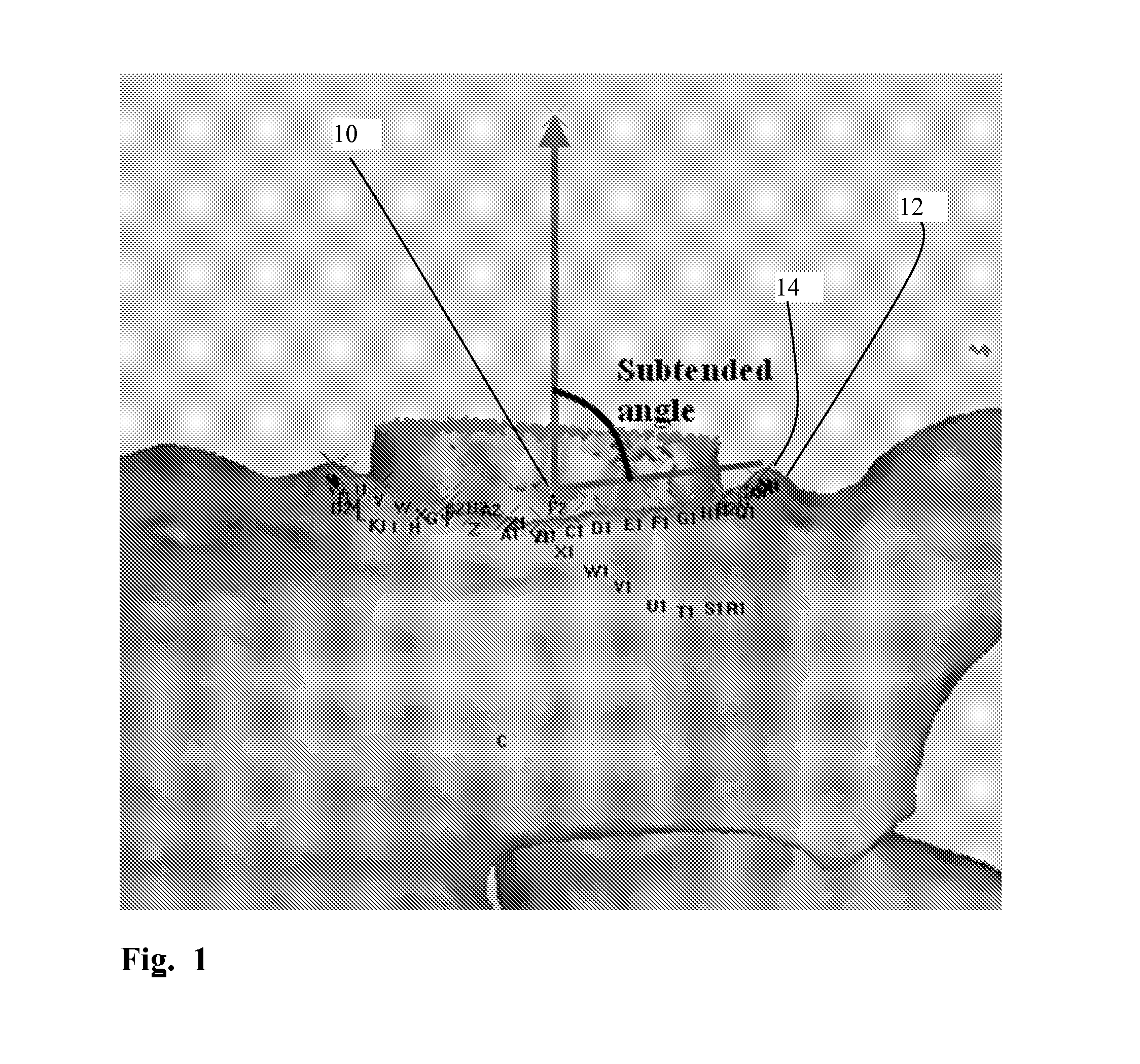
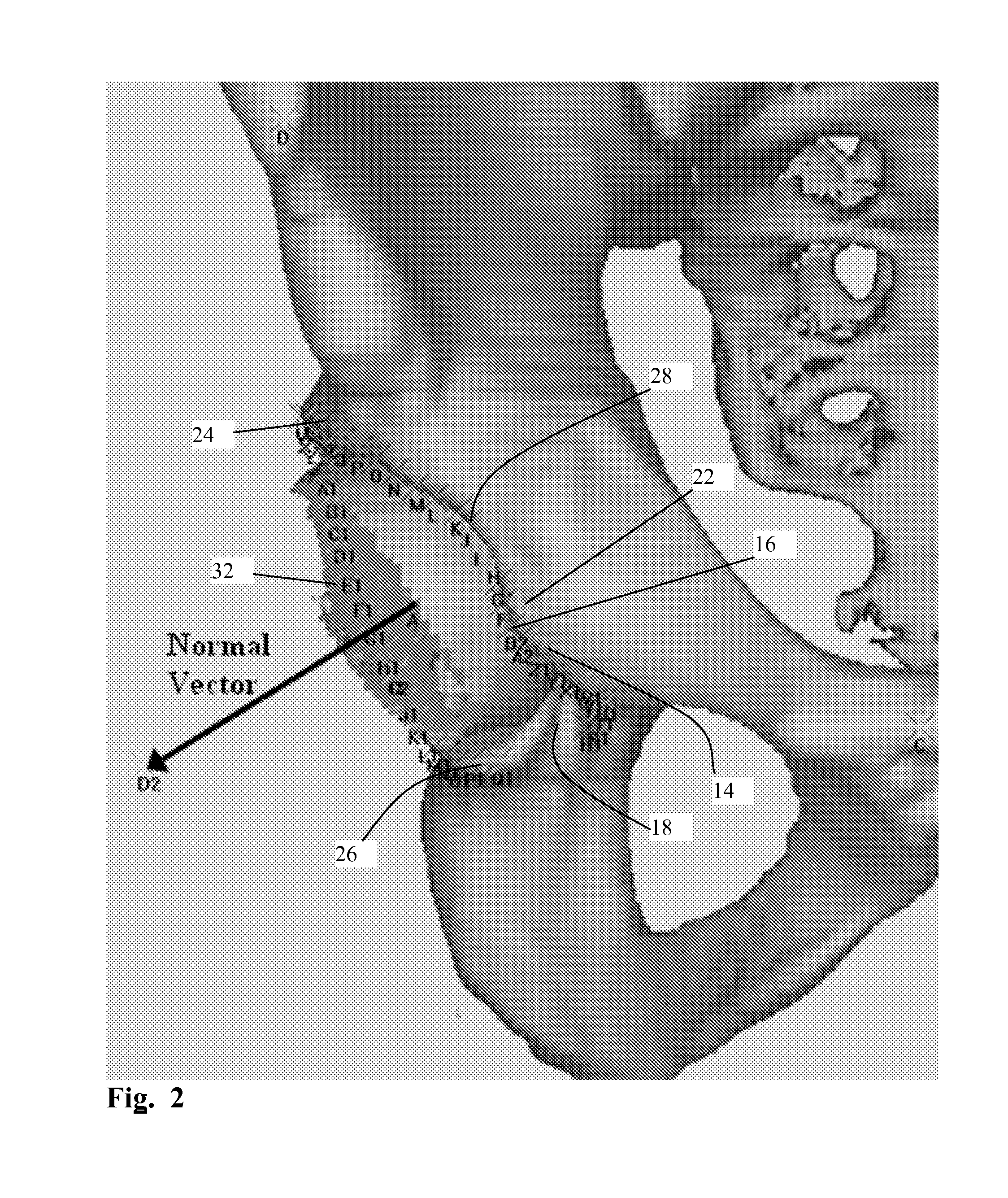
[0069]Referring to FIGS. 1 to 3 the centre 10 of the acetabulum 12 was defined as the centre of a best-fit sphere fitted through points in the articulating part of the acetabular socket; i.e. the lunate surface. Markers, indicated on the drawings as A-Z, A1-Z1 etc, were then assigned to respective points around the whole of the acetabular rim 14 starting from the pubic end 16 and moving postero-superiorly. The acetabular notch 18 was also included in order to complete the cycle. A best fit plane was then fit...


PUM


Abstract

A method of locating an acetabular cup implant (100) in a pelvis comprises locating a plurality of reference points on the pelvis, defining a target location of the implant relative to the reference points, and placing the implant at the target location. A method of locating a femoral head implant (102) is also disclosed, together with associated guidance systems.

Description

CROSS-REFERENCE TO RELATED APPLICATIONS[0001]This application claims the priority filing benefit of International PCT Application PCT / GB2009 / 051488 filed Nov. 5, 2009 and published under PCT 21(2) in the English language; and Great Britain Patent Application Serial No. 0820219.4 filed Nov. 5, 2008.FIELD OF THE INVENTION[0002]The present invention relates to the resurfacing of hips, and in particular to the design of hip resurfacing implants, guidance systems for use when resurfacing hips, and surgical tools for use when resurfacing hips.BACKGROUND TO THE INVENTION[0003]The morphology, orientation, and position of the acetabular and femoral components of the hip joint are important determinants of its function. The success of the native hip is based on design parameters of these components that, within a normal range of motion, avoid bony and soft tissue impingement. The native acetabulum is not perfectly hemispherical, and its rim is not simply a circle but rather a 3D shape with a ...

Claims


Application Information

Patent Timeline
Patent Type & Authority Patents(United States)
IPC IPC(8): A61F2/34A61F2/36A61B17/16A61B17/17A61F2/46A61F2/30
CPCA61F2/3603A61B17/1668A61B17/175A61B34/20A61F2/34A61F2/4609A61B2034/2055A61B2090/3983A61F2002/30217A61F2002/30616A61F2002/30736A61F2002/30878A61F2002/349A61F2002/3443A61F2002/4627A61F2002/4632A61F2002/4685A61F2230/0067
Inventor WOZENCROFT, ROBERT MICHAELAMIS, ANDREW ARTHURCOBB, JUSTINDANDACHLI, WAEL
Owner IMPERIAL INNOVATIONS LTD
Why Eureka
Try Eureka