Multi-core optical fiber interconnection structure and method for manufacturing multi-core optical fiber interconnection structure

a multi-core optical fiber and interconnection structure technology, applied in the direction of optical elements, manufacturing tools, instruments, etc., can solve the problems of difficulty in applying the aforementioned pc coupling to each of the cores, and no conventional technology taking into account the reflection at the interconnection, so as to minimize the variation in the distance between pairs and minimize the variation in the loss of inter-core connection

Active Publication Date: 2017-02-14
SUMITOMO ELECTRIC IND LTD
View PDF11 Cites 5 Cited by
  • Summary
  • Abstract
  • Description
  • Claims
  • Application Information

AI Technical Summary

Benefits of technology

[0007]The present invention has been accomplished in order to solve the problem as discussed above, and it is an object of the present invention to provide a multi-core optical fiber interconnection structure capable of reducing reflection at an interconnection where respective end faces of first and second multi-core optical fibers are connected to each other.
[0010]As a second aspect applicable to the first aspect, the slanted end face of the first multi-core optical fiber and the slanted end face of the second multi-core optical fiber preferably face each other so as to minimize variation in inter-core connection losses of pairs of the cores each in the one-to-one correspondence relation.
[0011]As a third aspect applicable to at least any one of the first and second aspects, the slanted end face of the first multi-core optical fiber and the slanted end face of the second multi-core optical fiber preferably face each other so as to minimize variation in distance between pairs of the cores each in the one-to-one correspondence relation.
[0013]As a fifth aspect applicable to at least any one of the first to fourth aspects, the first multi-core optical fiber preferably has a first marker for specifying positions of the respective cores in the core arrangement on the plane normal to the first central axis. Likewise, the second multi-core optical fiber also preferably has a second maker for specifying positions of the respective cores in the core arrangement on the plane normal to the second central axis. Particularly, the first marker in the slanted end face of the first multi-core optical fiber is located in an end face region lying farther away from the other end face of the first multi-core optical fiber than a first reference plane including an intersection between the slanted end face of the first multi-core optical fiber and the first central axis and being normal to the first central axis. On the other hand, the second marker in the slanted end face of the second multi-core optical fiber is located in an end face region lying nearer to the other end face of the second multi-core optical fiber than a second reference plane including an intersection between the slanted end face of the second multi-core optical fiber and the second central axis and being normal to the second central axis. In this case, the slanted end faces of the first and second multi-core optical fibers are made to face each other so as to align the first marker and the second marker with each other, whereby the variation in core pitches of the pairs of the cores each in the one-to-one correspondence relation can be easily minimized.
[0019]The manufacturing method according to the twelfth aspect comprises: arranging the first and second multi-core optical fibers so that the slanted end face of the first multi-core optical fiber and the slanted end face of the second multi-core optical fiber face each other in a state in which the first central axis and the second central axis are substantially parallel to each other. Furthermore, the manufacturing method comprises: adjusting relative positions between the slanted end faces of the first and second multi-core optical fibers so as to minimize variation in inter-core connection losses of pairs of the cores each in the one-to-one correspondence relation, in a state in which the cores of the first multi-core optical fiber and the cores of the second multi-core optical fiber are kept each in the one-to-one correspondence relation.

Problems solved by technology

Namely, in the case of multi-core optical fibers having a plurality of cores extending along the central axis, in a common cladding, the cores are also located at positions except for the center in the end face and it is thus difficult to apply the aforementioned PC coupling to each of the cores.
There was no conventional technology taking account of reflection at the interconnection in optical connection between multi-core optical fibers.

Method used


Image

  • Multi-core optical fiber interconnection structure and method for manufacturing multi-core optical fiber interconnection structure
  • Multi-core optical fiber interconnection structure and method for manufacturing multi-core optical fiber interconnection structure
  • Multi-core optical fiber interconnection structure and method for manufacturing multi-core optical fiber interconnection structure

Examples


first embodiment

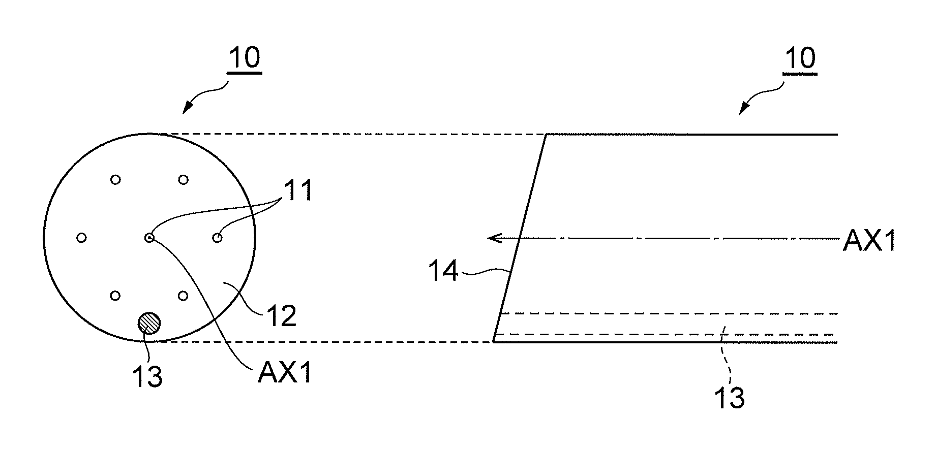
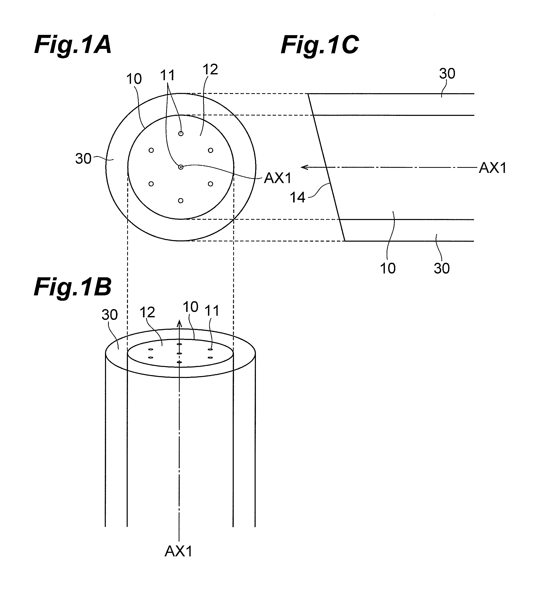
[0027]FIGS. 1A to 1C are drawings showing a configuration of one multi-core optical fiber (first multi-core optical fiber) 10 which can be applied to a multi-core optical fiber interconnection structure 1 according to the first embodiment. FIG. 1A is a view of the multi-core optical fiber 10 from a direction along a central axis AX1. FIG. 1B and FIG. 1C are views of the multi-core optical fiber 10 from two directions normal to the direction along the central axis AX1 and perpendicular to each other.

[0028]The multi-core optical fiber 10 has a plurality of cores 11 extending along the central axis AX1, in a common cladding 12. Each core 11 has the refractive index higher than that of the cladding 12 and can guide light. In the example shown in FIGS. 1A to 1C, one core 11 exists at the center in a circular section normal to the central axis AX1 of the multi-core optical fiber 10, and six cores 11 exist at equal intervals on the circumference of a circle centered at the central core 11....

second embodiment

[0038]FIGS. 3A and 3B are drawings showing a configuration of one multi-core optical fiber (first multi-core optical fiber) 10 applied to a multi-core optical fiber interconnection structure 2 according to the second embodiment. FIG. 3A is a view of the multi-core optical fiber 10 from a direction along the central axis AX1. FIG. 3B is a view of the multi-core optical fiber 10 from a direction normal to the central axis AX1.

[0039]The multi-core optical fiber 10 has a plurality of cores 11 extending along the central axis AX1, in a common cladding 12. Each core 11 has the refractive index higher than that of the cladding 12 and can guide light. In the example shown in FIGS. 3A and 3B, one core 11 exists at the center in a circular section normal to the central axis AX1 of the multi-core optical fiber 10 and six cores 11 exist at equal intervals on the circumference of a circle centered at the central core 11. Namely, the seven cores 11 are arranged at respective grid points of a tria...

modification examples

[0050]The present invention does not have to be limited to the above embodiments but can be modified in many ways. For example, the seven cores were arranged in the triangle grid pattern in the first and second embodiments, but the number of cores and the core arrangement in the multi-core optical fibers do not have to be limited to this configuration. The number of cores may be not more than 6 or not less than 8. The core arrangement may be determined from a variety of forms, e.g., arrangement of a rectangular grid pattern, arrangement on the same circumference, and so on.

[0051]In the second embodiment, one marker was the one that can be optically recognized on the end face, but the number, form, and arrangement of marker do not have to be limited to this configuration. A variety of modification examples can be contemplated; e.g., two or more markers are arranged so as to facilitate formation of the slant end faces.

[0052]The first and second embodiments were the examples to connect...


PUM

PropertyMeasurementUnit
angleaaaaaaaaaa
slant anglesaaaaaaaaaa
slant angleaaaaaaaaaa

Abstract

A multi-core optical fiber interconnection structure has a first multi-core optical fiber with a slanted end face and a second multi-core optical fiber with a slanted end face. In a state in which the slanted end faces face each other, each of cores of the first multi-core optical fiber is optically coupled to a corresponding one of cores of the second multi-core optical fiber in a one-to-one correspondence relation. The facing condition between the slanted end faces is adjusted so as to minimize variation in core pitches of pairs of the cores each in the one-to-one correspondence relation.

Description

[0001]This application claims the benefit of U.S. Provisional Application No. 61 / 682,411 filed Aug. 13, 2012, which is incorporated by reference herein in the entirety.BACKGROUND OF THE INVENTION[0002]Field of the Invention[0003]The present invention relates to a multi-core optical fiber interconnection structure and a method for manufacturing the multi-core optical fiber interconnection structure.[0004]Related Background of the Invention[0005]PC (Physical Contact) coupling is known as a method for optically connecting end faces of ordinary single-core optical fibers. In order to reduce reflection at an interconnection by PC coupling, it is necessary to keep an end face of a core of one single-core optical fiber in contact with an end face of a core of the other single-core optical fiber. Since each single-core optical fiber has only one core at the center in the end face, the end faces are polished in convex shape so as to form tops in central regions of the end faces of the respec...

Claims


Application Information

Patent Timeline
Patent Type & Authority Patents(United States)
IPC IPC(8): G02B6/38G02B6/36G02B6/42
CPCG02B6/3885G02B6/3652G02B6/3822G02B6/4224Y10T29/49826
Inventor SASAOKA, EISUKE
Owner SUMITOMO ELECTRIC IND LTD
Why Eureka
Try Eureka