Piezoelectric component and method for producing a piezoelectric component

a technology of piezoelectric components and piezoelectric components, which is applied in piezoelectric/electrostrictive/magnetostrictive devices, basic electric elements, electric apparatus, etc., can solve problems such as lowering the curie temperature of ceramic materials, and achieve the effect of improving properties

Active Publication Date: 2017-02-14
EPCOS AG
View PDF21 Cites 6 Cited by
  • Summary
  • Abstract
  • Description
  • Claims
  • Application Information

AI Technical Summary

Benefits of technology

[0009]Furthermore, a combined donor-acceptor doping at the B sites, in other words doping with W and RE, may bring about an increase in the concentration of the vacancies V″, governed by the incorporation of RE acceptor centers. At the same time, during sintering, a correspondingly high concentration of oxygen vacancies, VO, may be induced. With a doping concept of this kind, owing to the increased defect concentration, sufficient sinter densification of the piezoelectric ceramic may be achieved at temperatures of as low as about 950° C., and the grain growth that is essential for the development of advantageous piezoelectric properties may be considerably increased. The donor-acceptor ratio here may be set such as to produce a slight excess of vacancies at A sites in the finished ceramic. The oxygen vacancy concentration induced by RE centers during sintering is then no longer present in the finished ceramic.
[0039]According to one embodiment, in the method it is possible to select x=0.0295, y=0.0211, z=0.475, a=0.00753, b=0.0095 and RE=Yb, and so in method step D) at least one piezoelectric ceramic layer comprising Pb0.9451V0.00128″Cu0.003Ba0.0295Sr0.0211[Ti0.467Zr0.516W0.00753Yb0.0095]O3 is produced. This ceramic material has enhanced piezoelectric properties, such as a high density, high deflection parameters, and a large average grain diameter.

Problems solved by technology

The doping with Ba and / or Sr may result in a lowering of the Curie temperature of the ceramic material.

Method used


Image

  • Piezoelectric component and method for producing a piezoelectric component
  • Piezoelectric component and method for producing a piezoelectric component
  • Piezoelectric component and method for producing a piezoelectric component

Examples


Embodiment Construction

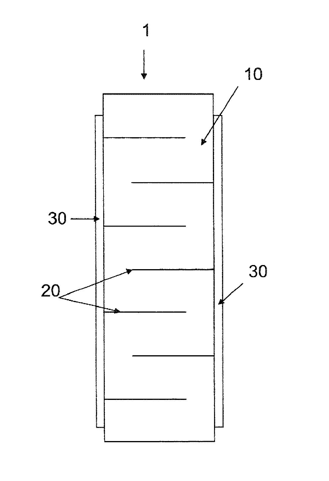
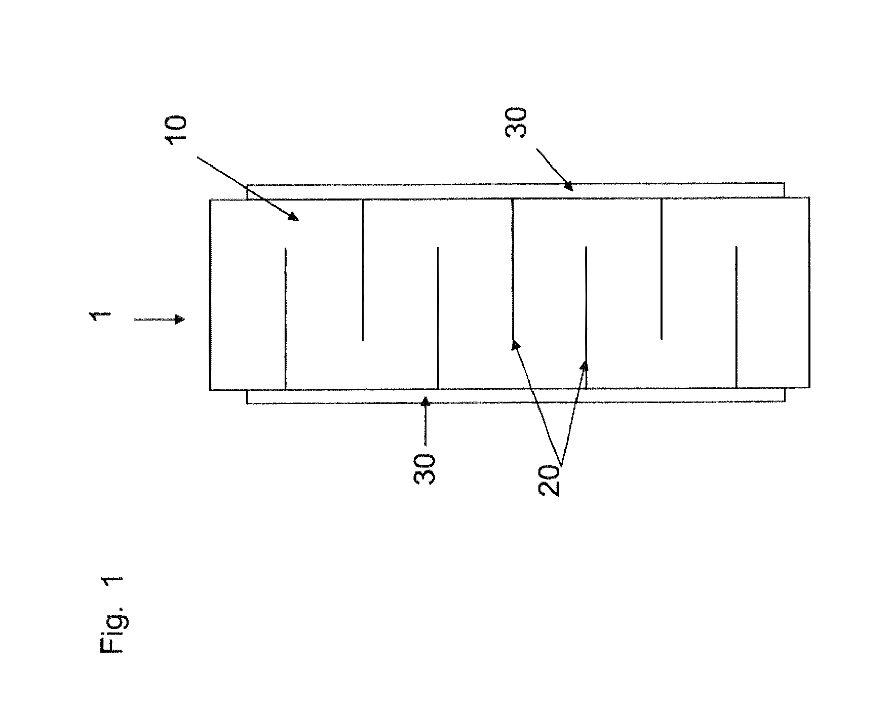
[0046]FIG. 1 shows a schematic side view of a piezoelectric component in the form of a multilayer component, as a piezoactuator. The component has a stack 1 of piezoelectric ceramic layers 10, disposed one atop another, with internal electrodes 20 between them. The internal electrodes 20 are designed as electrode layers. The piezoelectric ceramic layers 10 and the internal electrodes 20 are disposed one atop another.

[0047]In the embodiment shown here, the external electrodes 30 are disposed on opposite side faces of the stack 1, and run in stripe form along the stack direction. The external electrodes 30 comprise, for example, Ag or Cu and may be applied to the stack 1 as a metal paste, and baked.

[0048]The internal electrodes 20 run along the stack direction in alternation up to one of the external electrodes 30, with spacing from the second external electrode 30. In this way, the external electrodes 30 are electrically connected in alternation with the internal electrodes 20 along ...


PUM

PropertyMeasurementUnit
grain sizeaaaaaaaaaa

Abstract

A piezoelectric component has at least one piezoelectric ceramic layer and at least one electrode adjacent the piezoelectric ceramic layer. The piezoelectric ceramic layer has a piezoelectric ceramic material of the general formula Pb1-x-y-[(2a-b) / 2]-p / 2V[(2a-b) / 2-p / 2]″CupBaxSry[(TizZr1-z)1-a-bWaREb]O3, where 0≦x≦0.035, 0≦y≦0.025, 0.42≦z≦0.5, 0.0045≦a≦0.009, 0.009≦b≦0.011, 2a>b, p≦2a−b, RE is a rare earth metal, and V″ is a Pb vacancy.

Description

[0001]This patent application is a national phase filing under section 371 of PCT / EP2012 / 064538, filed Jul. 24, 2012, which claims the priority of German patent application 10 2011 112 008.8, filed Aug. 30, 2011, each of which is incorporated herein by reference in its entirety.TECHNICAL FIELD[0002]A piezoelectric component and a method for producing a piezoelectric component are specified.BACKGROUND[0003]Piezoelectric components such as piezoelectric multilayer components are used, for example, as actuators in fuel injection systems.SUMMARY OF THE INVENTION[0004]At least one embodiment of the invention provides a piezoelectric component having improved properties. At least one further embodiment of the invention provides a method for producing a piezoelectric component having improved properties.[0005]A piezoelectric component is specified that has at least one piezoelectric ceramic layer and at least one electrode adjacent the piezoelectric ceramic layer, the piezoelectric ceramic...

Claims


Application Information

Patent Timeline
Patent Type & Authority Patents(United States)
IPC IPC(8): H01L41/08H01L41/187C04B35/493H01L41/273C04B35/638H01L41/047C04B35/626
CPCH01L41/187C04B35/493C04B35/6261C04B35/62685C04B35/638H01L41/0471H01L41/0477H01L41/1876H01L41/273C04B2235/3213C04B2235/3215C04B2235/3224C04B2235/3225C04B2235/3258C04B2235/3281C04B2235/5445C04B2235/658C04B2235/6582C04B2235/6584C04B2235/6588C04B2235/768C04B2235/77C04B2235/786Y10T29/42H10N30/871H10N30/877H10N30/8554H10N30/053H10N30/853C04B35/491C04B35/62222C04B35/6262C04B35/62645C04B35/6303C04B35/64C04B41/009C04B41/5111C04B41/88C04B2235/3236C04B2235/3239C04B2235/3249C04B2235/3296C04B2235/656C04B2235/96
Inventor GLAZUNOV, ALEXANDERFELTZ, ADALBERT
Owner EPCOS AG
Why Eureka
Try Eureka