
High frequency circuit module

a high-frequency circuit and module technology, applied in the direction of transmission, electrical equipment, etc., can solve the problems of inaccurate impedance matching, limited adjustable impedance range, and higher transmission loss in some frequency bands, and achieve the effect of less loss and more accurate achievement of desired impedan

Active Publication Date: 2017-02-14
MURATA MFG CO LTD
View PDF36 Cites 1 Cited by
  • Summary
  • Abstract
  • Description
  • Claims
  • Application Information

AI Technical Summary

Benefits of technology

The present invention is related to a high frequency circuit module which includes a variable matching circuit. This circuit has a configuration in which an inductor is connected between the antenna port and ground. The main effect of this is that it allows for optimal impedance matching across a wide frequency range, resulting in reduced transmission loss.

Problems solved by technology

However, such a variable matching circuit including an inductor connected between the antenna port PANT and the ground as the one described above has a limited adjustable impedance range because of including that inductance.
This poses an issue of higher transmission loss in some of the frequency bands (that prevents accurate impedance matching) when the impedance matching is performed for respective ones of the plural kinds of frequency bands existing across a wide frequency range.

Method used


Image

  • High frequency circuit module
  • High frequency circuit module
  • High frequency circuit module

Examples


Embodiment Construction

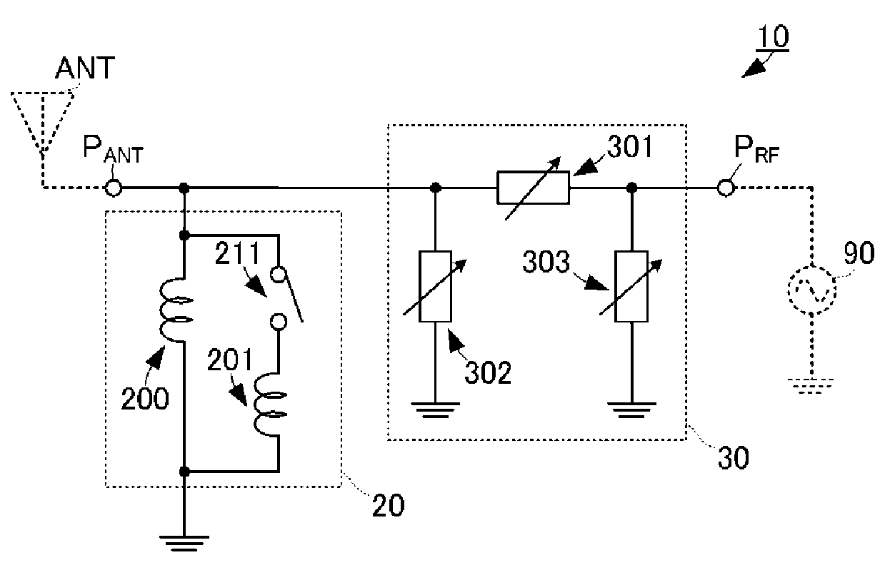
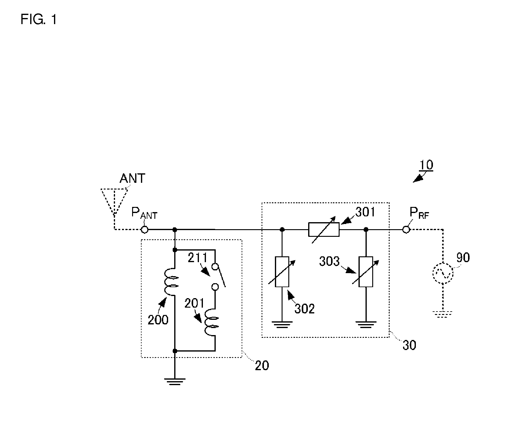
[0044]A high frequency circuit module according to a first preferred embodiment of the present invention is described with reference to the drawings. FIG. 1 is a circuit diagram of the high frequency circuit module according to the first preferred embodiment of the present invention.

[0045]A high frequency circuit module 10 includes a variable inductance circuit portion 20 and a reactance circuit portion 30.

[0046]An antenna port PANT of the high frequency circuit module 10 is a port to connect an antenna ANT. A front-end port PRF is a port to connect a transceiver circuit (front-end circuit) 90.

[0047]The variable inductance circuit portion 20 is connected between the antenna port PANT and ground. The variable inductance circuit portion 20 includes an inductor 200, an inductor 201, and a switch 211. The inductor 200 corresponds to a first inductor in preferred embodiments of the present invention, and the inductor 201 corresponds to a second inductor in preferred embodiments of the pr...


PUM


Abstract

A high frequency circuit module includes a variable inductance circuit portion and a reactance circuit portion. The variable inductance circuit portion is connected between an antenna port and ground. The variable reactance circuit is connected between the antenna port and a front-end port. The variable inductance circuit portion includes a first inductor, a second inductor, and a switch. The first inductor is connected between the antenna port and the ground. The second inductor and the switch are connected in series, and this series circuit is connected in parallel to the first inductor.

Description

BACKGROUND OF THE INVENTION[0001]1. Field of the Invention[0002]The present invention relates to high frequency circuit modules including variable matching circuits configured to perform impedance matching for antennas.[0003]2. Description of the Related Art[0004]Currently, various wireless communication devices are in practical use. These wireless communication devices are typically equipped with high frequency circuit modules that enable communications at a plurality of different kinds of frequency bands. Such a high frequency circuit module that enables communications at a plurality of different kinds of frequency bands includes an antenna capable of transmitting and receiving radio signals across a wide frequency range and a front-end circuit module capable of performing transmission processing and reception processing of communication signals at the plural kinds of frequency bands.[0005]In this high frequency circuit module, it is necessary to have a matching circuit for perfor...

Claims


Application Information

Patent Timeline
Patent Type & Authority Patents(United States)
IPC IPC(8): H04B1/46H04B1/04H04B1/18
CPCH04B1/18H04B1/0458
Inventor NAGUMO, SHOJIHARADA, TETSUROIWANAGA, MINORUNAGAI, TOMOHIRO
Owner MURATA MFG CO LTD
Learn More