Voltage/reactive power control apparatus, method, and voltage/reactive power control system

a technology of voltage/reactive power and control apparatus, applied in adaptive control, process and machine control, instruments, etc., can solve problems such as power quality degradation, and achieve the effects of less transmission loss, less transmission loss, and less transmission loss

Active Publication Date: 2020-09-29
HITACHI LTD
View PDF25 Cites 0 Cited by
  • Summary
  • Abstract
  • Description
  • Claims
  • Application Information

AI Technical Summary

Benefits of technology

[0020]According to the present invention, it is possible to perform a proper control even with a control delay or in a situation where the system conditions at the time of setting the voltage reference value may not be always reproduced.
[0021]More specifically, according to examples of the present invention, it is possible to, in the event of a control delay, re-calculate the control target value on the control side by generating the correction function for re-calculating the control target value with less transmission loss, for example, thereby implementing a control with less transmission loss as compared to the central control method and the hierarchical control method. In addition, it is possible to perform a control with less transmission loss in the entire system as compared to the individual control method.

Problems solved by technology

Therefore, it is feared that power flow in power systems will increase uncertainty, thereby resulting in degradation of power quality.

Method used


Image

  • Voltage/reactive power control apparatus, method, and voltage/reactive power control system
  • Voltage/reactive power control apparatus, method, and voltage/reactive power control system
  • Voltage/reactive power control apparatus, method, and voltage/reactive power control system

Examples


example 1

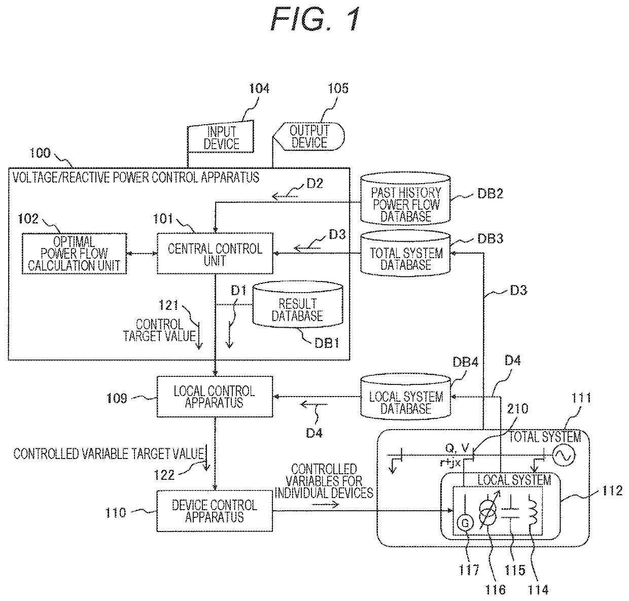
[0037]FIG. 1 is a block diagram illustrating an entire configuration of a voltage / reactive power control system including a voltage / reactive power control apparatus according to Example 1 of the present invention.

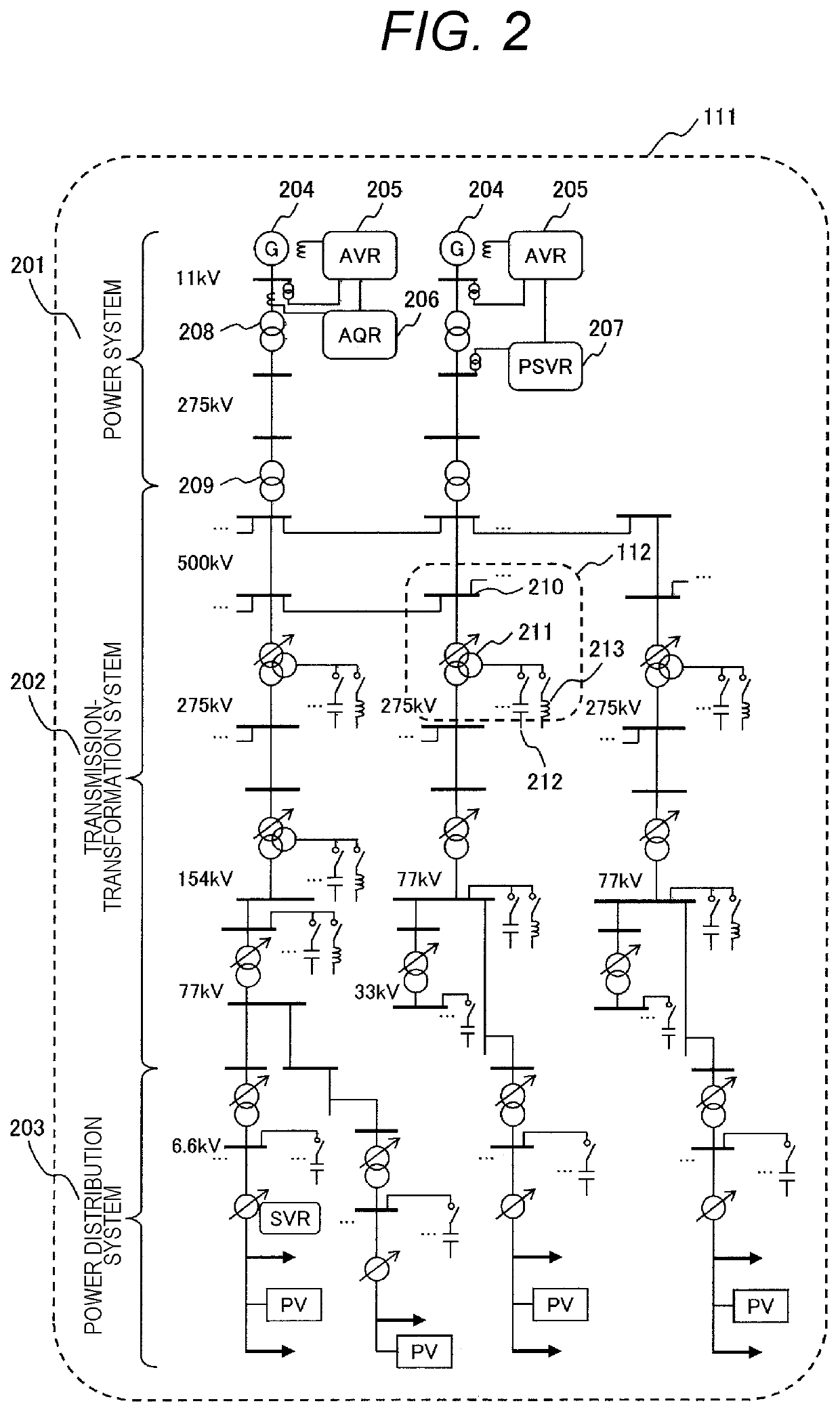
[0038]Referring to FIG. 1, a total system 111 in a power system as a monitoring and control target includes a plurality of local systems 112 as appropriately divided units. The local systems 112 include pluralities of shunt reactors 114 as phase modifying equipment, power capacitors 115, transformers with on-load tap changers 116, generators with automatic voltage regulators 117, and others. The local systems 112 can be said to be sub systems appropriately divided from the total system 111 in the power system from the viewpoint of voltage class or region.

[0039]A voltage / reactive power control apparatus 100 is configured to monitor and control the power system, and includes a central control unit 101, an optimal power flow calculation unit 102, a result database DB1, an inpu...

example 2

[0068]In contrast, Example 2 is a voltage / reactive power control apparatus according to the individual control method. In this case, Example 2 is a role-sharing system configuration in which the voltage / reactive power control apparatus is arranged for each local system to correct as appropriate the control target value and the correction function D1 to the local system obtained from the higher rank by using the local system data D4 from the local system database DB4 and control the voltage / reactive power control device in the local system.

[0069]FIG. 12 is a block diagram illustrating a configuration of a voltage / reactive power control apparatus according to Example 2 of the present invention. A voltage / reactive power control apparatus 130 in Example 2 includes a local control apparatus 109 with a control target value correction unit 131 and a device control apparatus 110. A past history power flow database DB2, a total system database DB3, and a local system database DB4 are connect...

example 3

[0073]Example 3 is a voltage / reactive power control apparatus according to the central control method as well. The central control method in Example 3 is different from that in Example 1 in that the voltage / reactive power control apparatus includes a local control apparatus. Therefore, the device control apparatus is given a signal allowing for the correction of controlled variable fluctuation resulting from the time difference between the time of optimal power flow calculation and the time of device control.

[0074]A voltage / reactive power control apparatus 100 in Example 3 illustrated in FIG. 14 includes a local control apparatus 109. In this configuration, the central control apparatus 101 calculates the control target value 121 to be passed from the optimal power flow calculation unit 102 to the local control apparatus 109 with the total system data D3 from the total system database DB3 as an input, and transmits the same to the local control unit 109. In addition, with the past h...


PUM


Abstract

There is provided a voltage / reactive power control device, method, and a voltage / reactive power control system that allow a proper control even with a control delay or in a situation where the system conditions at the time of setting the voltage reference value may not be always reproduced. A voltage / reactive power control system is applied to a power system in which a monitoring point is set in a local system divided as appropriate from the power system and the local system includes a voltage / reactive power control device capable of adjusting voltage and reactive power at the monitoring point. The voltage / reactive power control system includes: a central control unit that sets a control target value of the voltage and reactive power at the monitoring point in the local system based on optimal power flow calculation using total system data on the power system, generates a correction function to correct the control target value in accordance with a change in state of the power system relating to the monitoring point by using past history information on the states of the power system, and outputs the control target value and at least one or more correction functions; a local control apparatus that, when the control target value is different from system data on the local system, uses the correction function to calculate a controlled variable for the voltage / reactive power control device necessary to attain the control target value; and a device control apparatus that controls the voltage / reactive power control device in accordance with the controlled variable from the local control apparatus.

Description

TECHNICAL FIELD[0001]The present invention relates to a voltage / reactive power control apparatus, method, and a voltage / reactive power control system for bringing the voltage at monitoring points into an allowable range and keeping reactive power in balance in a power system.BACKGROUND ART[0002]With growing energy demand and electricity deregulation, power systems have been increasingly expanded in scale, and power providers and power sources have been diversified and decentralized. Therefore, it is feared that power flow in power systems will increase uncertainty, thereby resulting in degradation of power quality. Accordingly, there is a need for high-quality and stable voltage management and effective power supply.[0003]In a power system, with reactive power and voltage varying with state changes in load, there has been conventionally performed a voltage / reactive power control to minimize power loss while satisfying the rated voltage value and the restrictions on generator reactiv...

Claims


Application Information

Patent Timeline
Patent Type & Authority Patents(United States)
IPC IPC(8): H02J3/18H02J3/00H02J13/00G05B13/04H02J3/12
CPCH02J3/12G05B13/041H02J13/00H02J13/00007H02J3/00H02J3/18Y02E40/70H02J2203/20Y04S10/22Y02E40/30Y04S40/20Y04S10/50Y04S20/00Y02B90/20Y02E60/00Y04S40/121H02J3/381H02J3/48H02J3/50
Inventor MIYAKE, TOSHIYUKIKURODA, EISUKEYATSU, MASAHIRO
Owner HITACHI LTD
Why Eureka
Try Eureka