
Proximity based sub-pooling of network devices in mobile wireless networks

a network device and mobile wireless technology, applied in the direction of wireless network protocols, network traffic/resource management, electrical equipment, etc., can solve the problems of additional transport layer latency, unequal distribution of mme subscriber load across the mmes in the pool,

Active Publication Date: 2017-02-21
AT&T INTPROP I LP
View PDF27 Cites 12 Cited by
  • Summary
  • Abstract
  • Description
  • Claims
  • Application Information

AI Technical Summary

Benefits of technology

The patent text describes a method for selecting network devices in mobile wireless networks to ensure that they are geo-redundant, meaning they are spread across different locations to prevent outages caused by catastrophic events. The method uses a proximity-based selection process to select the most suitable network devices based on their distance to the location where they are hosted. This reduces the impact on network users in case of an outage. The patent also describes a method for determining transport latency in the network to optimize communication connectivity. Overall, the patent provides technical means for ensuring resilience and efficiency in wireless networks.

Problems solved by technology

Using a geographically more remote MME generally incurs additional transport layer latency.
It is foreseeable that such additional latencies could impact LTE signaling, such as S1-MME SCTP rwnd, call setup time, additional transport network infrastructure, transport network overheads and improper utilization of the backhaul network elements that could be subjected to instantaneous traffic loading.
It is understood that the proposed configurations disclosed herein can lead to unequal MME subscriber load distribution across the MMEs in the pool.

Method used


Image

  • Proximity based sub-pooling of network devices in mobile wireless networks
  • Proximity based sub-pooling of network devices in mobile wireless networks
  • Proximity based sub-pooling of network devices in mobile wireless networks

Examples


Embodiment Construction

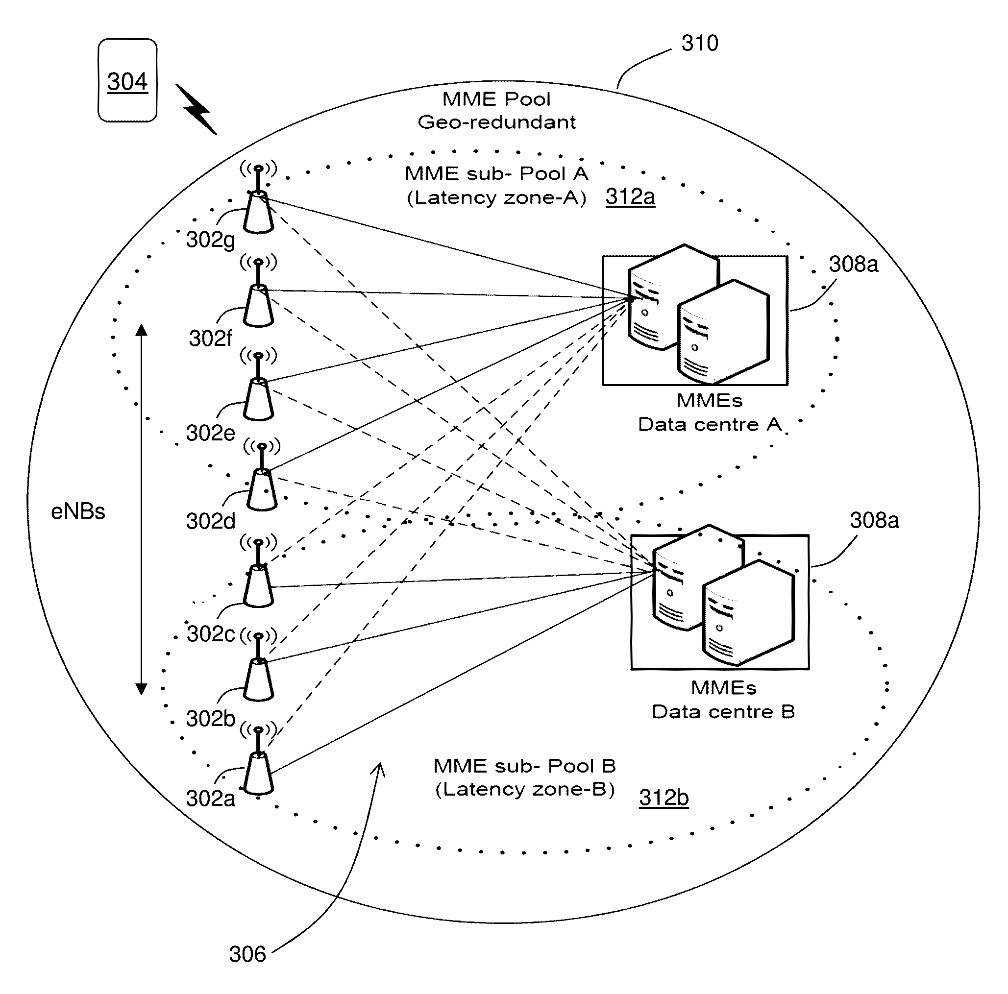
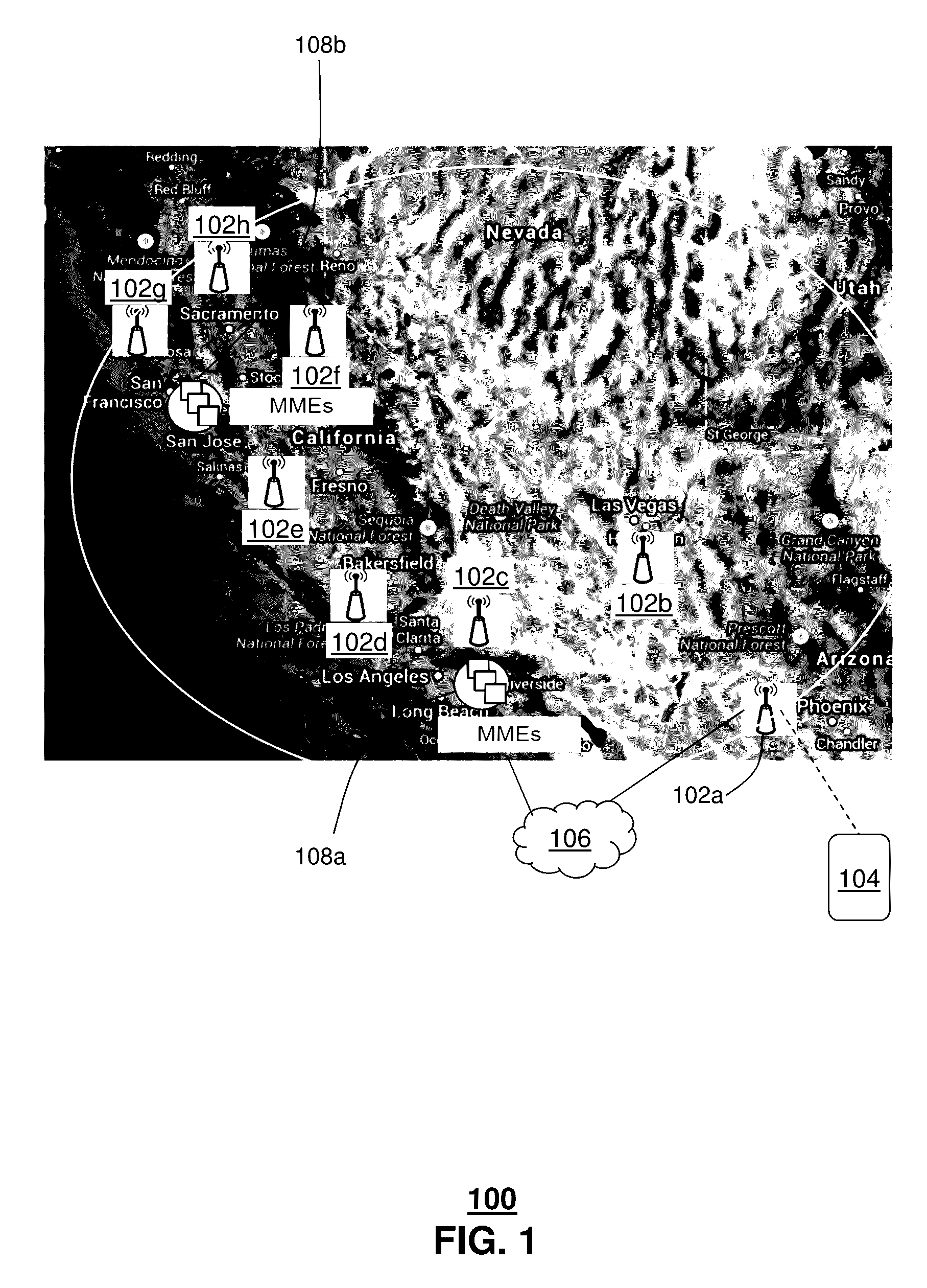
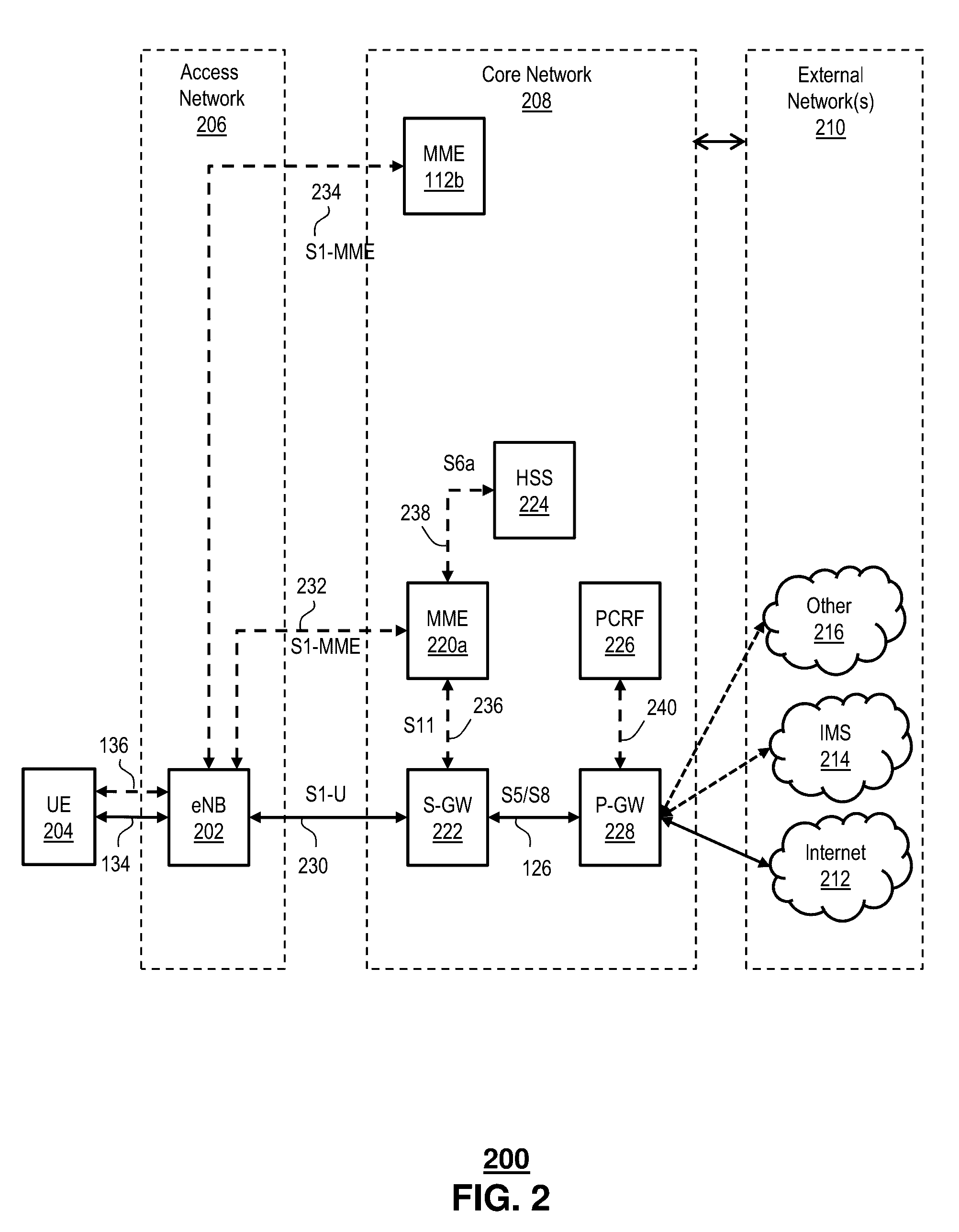
[0013]The subject disclosure describes, among other things, illustrative embodiments for selecting wireless core network nodes, such as MMEs, to facilitate end-to-end communications. In one or more embodiments, the network node, e.g., MME selection can be a proximity-based selection process. In one or more embodiments, the proximity-based selection process for the network nodes, e.g., MMEs can be based on timing parameters, such as round trip delays or times during an S1 setup (e.g., Stream Control Transmission Protocol (SCTP) signaling Smooth Round Trip Time (SRTT)). The same proximity-selection process concept can be extended to select other wireless core nodes, e.g., SGW, PGW, HSS, GMLC, MTC-IWF, etc.

[0014]In one or more embodiments, methods and systems can determine transport latency in a backhaul network between a wireless base station and a number of redundant core network nodes of a wireless communications network. At least some of the redundant core network nodes can be geog...


PUM


Abstract

Aspects of the subject disclosure may include, for example, determining message transfer delays based on transport layer control information associated with network traffic of a backhaul network coupled between a number of core network nodes of a wireless network and a wireless access node of the wireless network. The message transfer delays are representative of the network traffic between the core network nodes and the wireless access node. Weighting factors are assigned to the core network nodes based on the message transfer delays. The weighting factors are exposed to a scheduler that identifies a first group of core network nodes and a second group of core network nodes based on the weighting factors. The wireless access node preferentially establishes communications via the first group of core network nodes. The wireless access node establishes communications via the second group, responsive to an inability to establish communications via any core network nodes the first group. Other embodiments are disclosed.

Description

FIELD OF THE DISCLOSURE[0001]The subject disclosure relates to proximity based sub-pooling of network devices in mobile wireless networks.BACKGROUND[0002]Network devices, such as core network control plane entities or core network nodes of a mobile wireless network, can be deployed in a geo-redundant pool. The geo-redundant pool provides network devices spread across different geographical locations, e.g., hosted in data centers in different cities. In mobile wireless network applications, base transceiver stations can establish connectivity to the network devices spread across the different geographical locations. Such geographic isolation protects network users from outages that might otherwise result from a catastrophic event, e.g., a fire, earthquake, flood, at any one location. In view of such an event, network traffic can simply be directed to other network devices in the pool locations that otherwise unaffected by the event.BRIEF DESCRIPTION OF THE DRAWINGS[0003]Reference wil...

Claims


Application Information

Patent Timeline
Patent Type & Authority Patents(United States)
IPC IPC(8): H04B7/00H04W28/02H04W24/08H04W80/06
CPCH04W28/0236H04W24/08H04W80/06H04L45/46H04L45/22H04L47/122H04L47/629H04L47/27H04L47/283
Inventor SEENAPPA, VIKRAMKODAYPAK, RAJENDRA PRASADWANG, JIANSONG
Owner AT&T INTPROP I LP
Learn More