
Avoiding dazzle from lights affixed to an intraoral mirror, and applications thereof

Active Publication Date: 2017-03-07
DENTAL SMARTMIRROR INC
View PDF7 Cites 32 Cited by
  • Summary
  • Abstract
  • Description
  • Claims
  • Application Information

AI Technical Summary

Benefits of technology

This patent integrates a camera into an intraoral mirror, which is used by dental professionals to view the mouth. The camera allows the dentist to record and display what they see in the mirror. This technology may be used to capture dental status and create a digital dental impression. The technical effect of this is that it provides a more efficient and convenient way to record dental information.

Problems solved by technology

Viewing objects in a mouth directly is difficult due to a limited, or perhaps nonexistent, line of sight.
But, due to frequent use and sterilization, the mirror eventually loses some of its clarity and its reflectiveness, thus needing replacement.
However, because these displays are the only viewfinder for the cameras, their use adds time to a dental appointment.
This may seem a minor hassle, but in the busy environment of a dental clinic, it reduces the frequency of capturing images.
This light might be harmful to the eye, therefore an eye protector is used by the healthcare provider while using the light cure.
Entering data into a patient's medical record takes time.
The computer processing power required to produce such digital imprint in a reasonable amount of time is, therefore, substantial.
The technology implemented in the scanner head affects both accuracy and speed.
In practice, achieving accurate depth measurements through image analysis in a short period of time is challenging since much of the information that is extracted from images tends to exhibit geometric noise, due to either distortion in the image capturing process, or uneven reflection of the illumination of intraoral objects.
The presence of saliva in an intraoral environment, is an additional, and sometimes substantial hurdle to the accuracy of the process, since it may cause some areas to exhibit specular reflection even if otherwise they would not.
Using a multitude of captured images of an intraoral object from various angles, will greatly assist the triangulation accuracy, but unfortunately will extend the computational effort and hence the amount of time and processing power required for accurate calculation.

Method used


Image

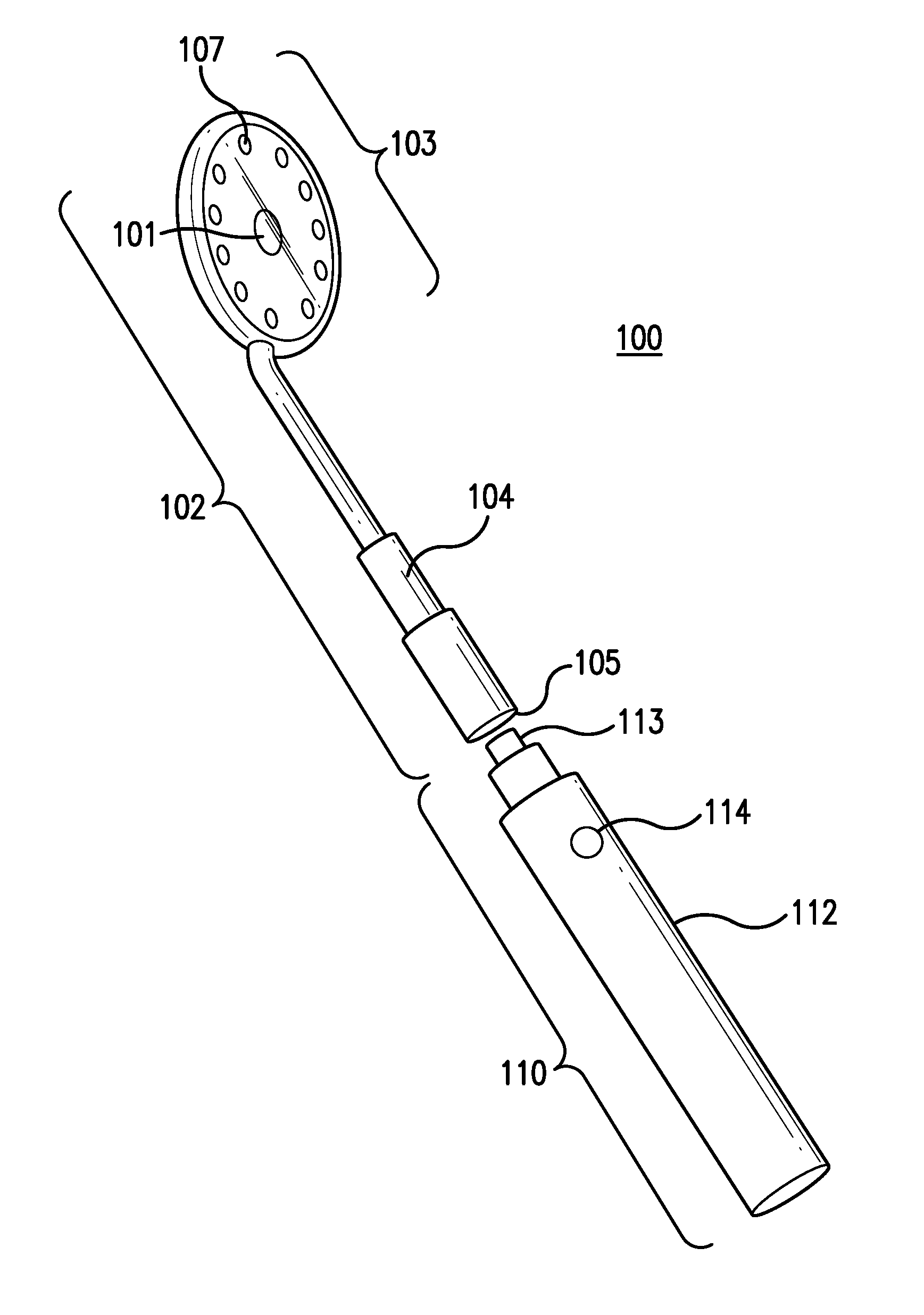
  • Avoiding dazzle from lights affixed to an intraoral mirror, and applications thereof
  • Avoiding dazzle from lights affixed to an intraoral mirror, and applications thereof
  • Avoiding dazzle from lights affixed to an intraoral mirror, and applications thereof

Examples


Embodiment Construction

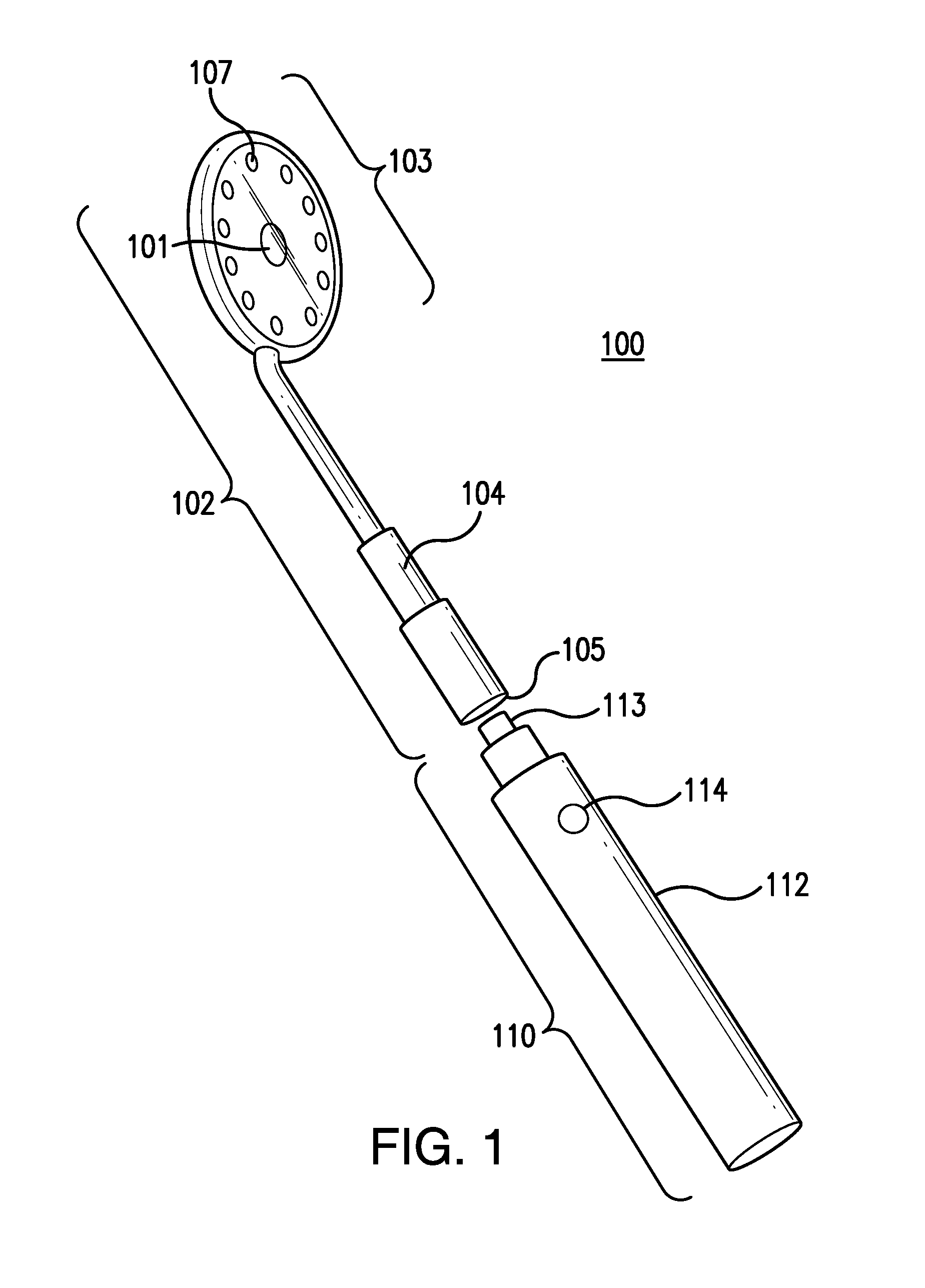
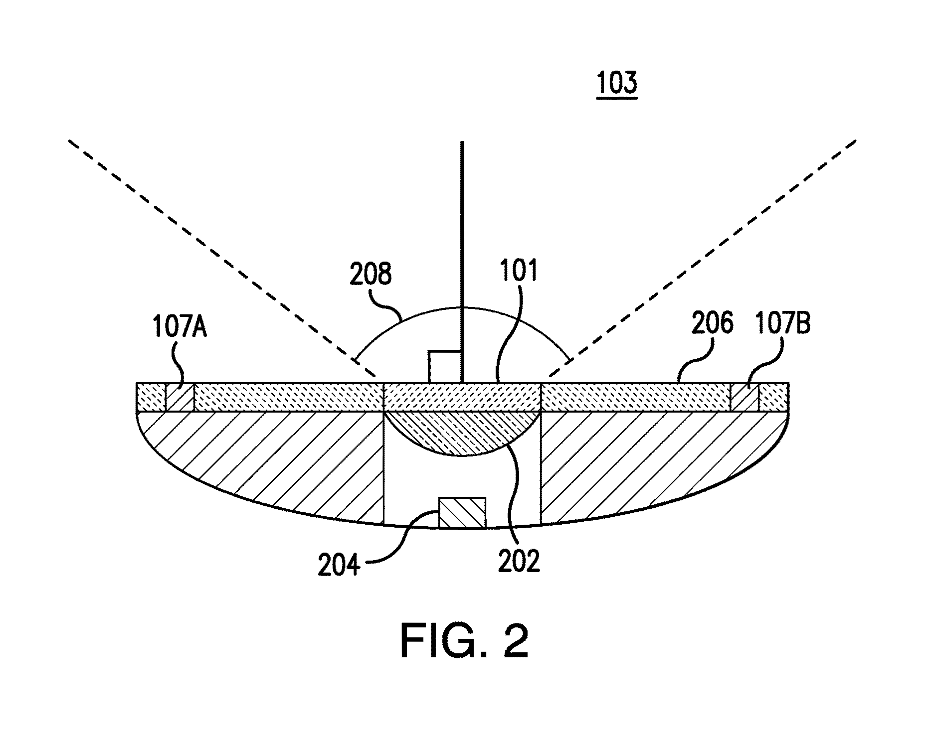
[0058]The detailed description that follows is divided into ten sections. First, an intraoral mirror with an integrated camera is described with respect to FIGS. 1 and 2. Second, how the intraoral mirror is used as a viewfinder for the camera is described with respect to FIGS. 3, 4, 5A-C, 6A-B and FIGS. 7A-C. Third, systems and methods that utilize the intraoral mirror are described with respect to FIGS. 8-16. Fourth, how the intraoral mirror is used to capture a patient's dental status is described with respect to FIGS. 17A-C and 18A-C. Fifth, how the intraoral mirror is used to capture a patient's dental impression is described with respect to FIGS. 19A-B. Sixth, how the status and impressions are generated incrementally is described with respect to FIG. 20 and FIGS. 21A-B. Seventh, a system for capturing a patient's status and generating a patient's dental impression is described with respect FIG. 22. Eighth various methods for adjusting illumination of the intraoral mirror are d...


PUM


Abstract

Disclosed embodiments integrate a camera into an intraoral mirror. Integrating a camera into an intraoral mirror provides an efficient way to record and display what is visible to the healthcare provider in the mirror.

Description

BACKGROUND[0001]Field[0002]This field is generally related to dental instruments.[0003]Related Art[0004]Intraoral mirrors, also known as mouth mirrors, are among the most functional and frequently used of dental instruments. Viewing objects in a mouth directly is difficult due to a limited, or perhaps nonexistent, line of sight. Intraoral mirrors allow a health care provider (HCP), for example dentist, hygienist and others, to indirectly view teeth and other objects in a patient's mouth, such as the patient's gums and tongue, by observing their reflections in a mirror. Health care providers use the intraoral mirror for a variety of tasks, including, but not limited to, evaluation and diagnosis, treatment selection, and even to assist the treatment itself. A health care provider may use other tools, such as a dental hand piece, in conjunction with the mirror to conduct procedures, such as tooth preparation, when the procedures are conducted in areas that are not directly visible.[000...

Claims


Application Information

Patent Timeline
IPC IPC(8): A61B1/247G06K9/00H05B37/02H04N5/235A61B1/00A61B1/05A61B1/06A61B5/06A61B5/00A61C9/00A61C13/00A61C13/34G06T7/00H04N5/232H04N5/225G06T7/40H05B44/00
CPCA61B1/247G06T7/0081G06K9/00228H05B37/0227G06T7/408A61B1/00016A61B1/00032A61B1/00041A61B1/00105A61B1/05A61B1/0607A61B1/0676A61B5/067A61B1/063A61B5/0086A61B5/0088A61C9/0073A61C13/0004A61C13/34H04N5/2257H04N5/2354G06T2207/30036A61B1/00006A61B1/00034A61B1/045A61B1/0684A61C3/00A61B5/0022A61B2560/0456A61B2576/02G16H30/20G16H40/63G16H20/40A61B5/0079A61B5/1176A61B1/00045H05B45/22G16H30/40H05B47/00A61B1/0004A61B1/000095A61B1/0655H04N23/555H04N23/56H04N23/57H04N23/51H04N23/60A61B1/00009G16H40/67A61B5/0013A61B1/24G10L15/26H05B45/00H05B47/105G06V40/166H04N23/54H04N23/55H04N23/65H04N23/74H04N23/698A61B1/06H04L67/01H04L67/02H04L67/025H04L67/125A61C19/04A61C2204/005H04W12/73A61B5/0077A61B5/002H04L67/12G06T5/92A61B6/51G06F3/023G06F3/0334G06T3/40G06T3/60G06T2210/22G06T2210/41H04N7/183A61B1/00195F21V33/0068F21W2131/202G02B27/144G06T7/0016G06T17/20G06T2207/10048A61B1/00087A61C19/004G06T7/337A61B5/061A61B5/065G06T3/4038G06T2200/32G06T2207/10116G06T2207/20208G06T2207/20212G06T7/11G06T7/0012
Inventor ELAZAR, GIDON ODEDHARKABI, DAN ZIDKIAHU
Owner DENTAL SMARTMIRROR INC
Learn More