Light load compression limiting fastening system

a technology of light load compression and fastening system, which is applied in the direction of threaded fasteners, screws, washers, etc., can solve the problems of structural or cosmetic damage to the fastened component, no stabilizing load for the upper surface of the fastened component, and the fastened component may experience a substantial level of compression, etc., to achieve the effect of light load on the fastened componen

Active Publication Date: 2017-03-07
ILLINOIS TOOL WORKS INC
View PDF16 Cites 12 Cited by
  • Summary
  • Abstract
  • Description
  • Claims
  • Application Information

AI Technical Summary

Benefits of technology

[0005]The fastening system of the present disclosure permits a fastening element such as a bolt or the like to be fastened down fully while still maintaining a relatively light load on a fastened component. This avoids over compression which may lead to damage or fatigue over time when using delicate materials.

Problems solved by technology

While such an arrangement provides a secure connection, the fastened component may experience a substantial level of compression as pressure is applied by the fastening element.
In severe situations, such compression may cause structural or cosmetic damage to the fastened component.
While sleeve inserts may provide a useful function, such elements do not provide any stabilizing load across the upper surface of the fastened component during connection.

Method used


Image

  • Light load compression limiting fastening system
  • Light load compression limiting fastening system
  • Light load compression limiting fastening system

Examples


Embodiment Construction

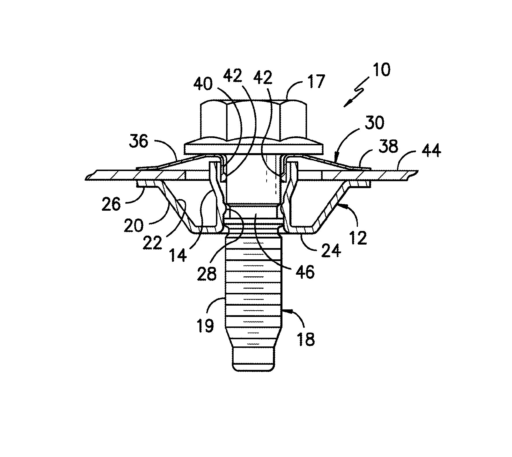
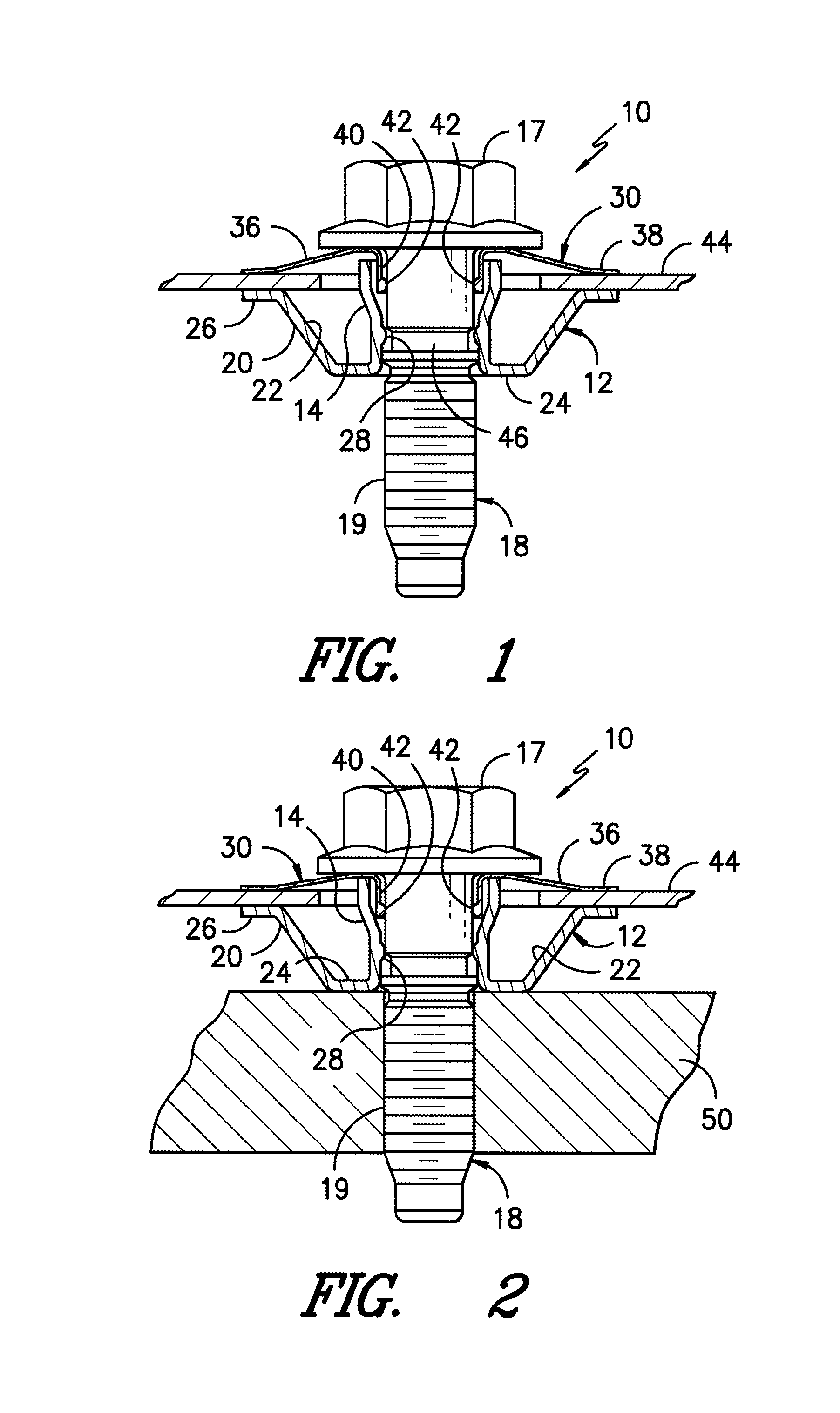
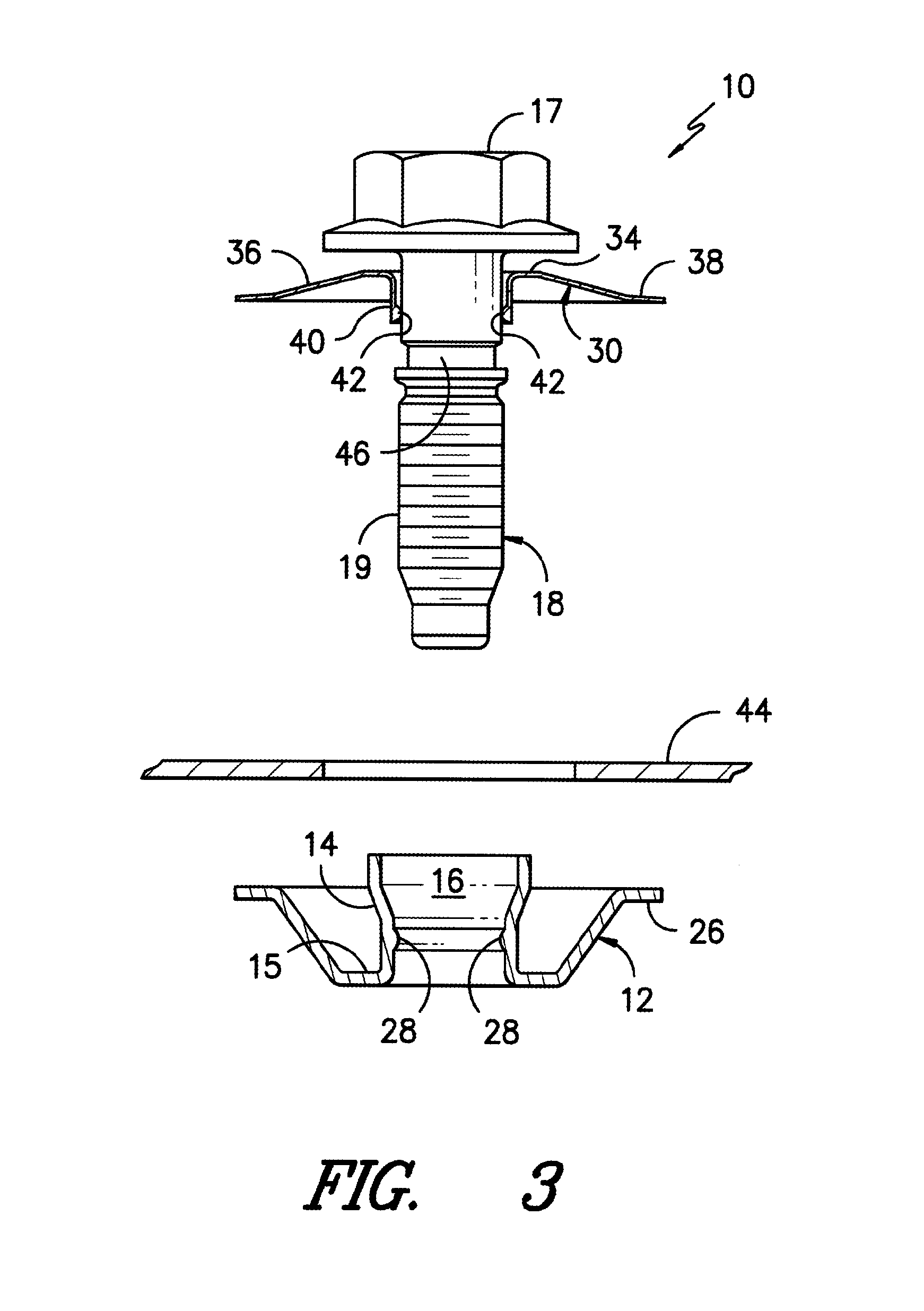
[0018]Reference will now be made to the drawings, wherein to the extent possible, like elements are designated by like reference numerals in the various views. Referring now jointly to FIGS. 1-3, an exemplary fastening system 10 is illustrated. As shown, in the exemplary construction the fastening system 10 includes a compression limiting sleeve 12 (i.e. bushing) of drawn metal or the like. By way of example only, the sleeve 12 may be formed from spring steel or the like, although other metals or polymers may be used if desired.

[0019]As best seen through joint reference to FIGS. 1 and 4, the sleeve 12 may have a substantially annular bowl shape defining a torus surrounding an axial hub 14. The axial hub 14 includes a central axial passageway 16 for receipt of a bolt 18. As shown, the bolt 18 may include a tool-engaging head 17 of polymeric geometry with a threaded shaft 19 extending downwardly from the head. In this regard, it is to be understood that the term “bolt” is meant to inc...


PUM


Abstract

A compression limiting fastening system incorporating a spring element and cooperating compression limiting sleeve adapted for substantially coaxial receipt of a fastening element through a fastened component so as to apply a relatively light load to an outer surface of the fastened component during the fastening operation. Once fastened down, the compression limiting sleeve supports the fastening load while the spring element applies a relatively light opposing load to the fastened component.

Description

CROSS-REFERENCE TO RELATED APPLICATIONS[0001]This application is a National Phase of International Application Number PCT / US2013 / 032891 filed Mar. 19, 2013 and claims the benefit of, and priority from, U.S. provisional application 61 / 613,147 filed Mar. 20, 2012. The contents of such priority application are hereby incorporated by reference in their entirety as if fully set forth herein.FIELD OF THE DISCLOSURE[0002]The present disclosure relates generally to connection assemblies, and more specifically to a fastening system for receipt of an elongated male fastening element through a fastened component so as to apply a relatively light load to the fastened component while the fastening element establishes a secure connection with an underlying mating structure. By way of example only, connection assemblies in accordance with the present disclosure may find application in the connection of relatively delicate trim elements or the like to underlying support structures during automotive...

Claims


Application Information

Patent Timeline
Patent Type & Authority Patents(United States)
IPC IPC(8): F16B5/00F16B29/00F16B43/00F16B39/26F16B5/02F16B41/00
CPCF16B29/00F16B5/00F16B5/0266F16B39/26F16B41/002F16B43/00
Inventor BISSET, JOHN D.HOLT, JASON D.OWENS, II, RONALD C.DECHANT, DANIEL A.
Owner ILLINOIS TOOL WORKS INC
Why Eureka
Try Eureka