
Lighting device

a technology of optical assembly and light source, which is applied in the direction of fault response, lighting and heating apparatus, instruments, etc., can solve the problems of occupying too much space and consuming a lot of energy for the light box, and the light emitted from the led source cannot extend far enough, so as to increase the reflectivity of the reflecting interface, reduce the effect of light waste and poor light

Inactive Publication Date: 2017-03-07
SIGNIFY HLDG BV
View PDF10 Cites 0 Cited by
  • Summary
  • Abstract
  • Description
  • Claims
  • Application Information

AI Technical Summary

Benefits of technology

The present patent aims to provide an optical assembly that can produce thinner and more uniform lights. The solution involves two aspects: firstly, the reflecting interface of the optical components is designed to gradually increase its reflectivity, resulting in more uniform lights. Secondly, the parallel arrangement of optical components in a radial shape improves the light uniformity by distributing the emitted light into as many different directions as possible. Furthermore, by engaging multiple modular optical assemblies with each other to form an array, even a large illuminated area can be provided with a uniform light distribution. The optical assembly can be made in a very small size, which lowers the cost, makes it easier to install in any architecture or object.

Problems solved by technology

However, a bigger space and more LED sources are needed for operation of the back-lit type; this type of light box occupies too much space and consumes a lot of energy.
Even if the edge-lit type can be made thinner, the light emitted from the LED sources cannot extend far enough if the box is too big.

Method used


Image

  • Lighting device
  • Lighting device
  • Lighting device

Examples


Embodiment Construction

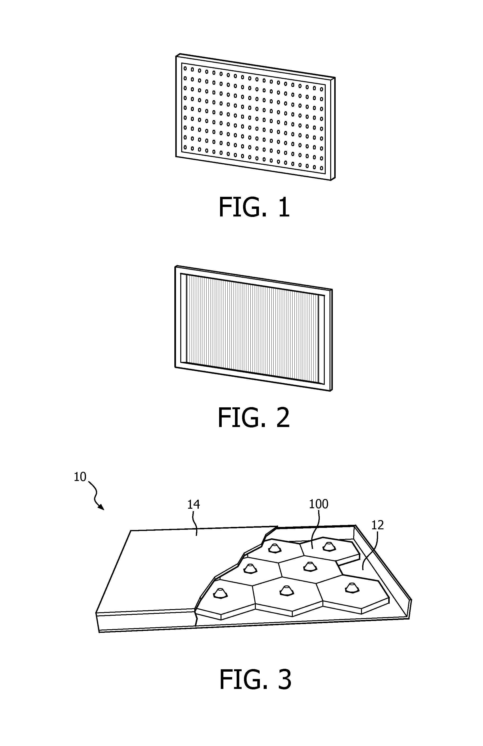
[0023]In the following description, the present invention is described with reference to a light box, but this by no means limits the scope of the invention; for example, the present invention could be described with reference to a shopping window or other applications where it is needed.

[0024]With reference to FIG. 3, the light box 10 comprises a front plate 12 and a back plate 14, both defining a space for a lighting device 100. The front plate is transparent; a diffuser may be provided in front of the front plate to further optimize the uniformity. The back plate 14 may be transparent or provided with reflecting materials. When a transparent back plate is used, the light beam generated behind the back plate, such as natural light or ambient light, can penetrate the whole lighting device, including the front plate, and eventually can be seen by people standing in front of the front plate, which can fulfill an energy saving function during daytime if the light box needs to be turne...


PUM


Abstract

The invention discloses an optical assembly comprising a plurality of optical components that are concentric to one another, each optical component having a partially reflective and partially transmissive interface with an oblique angle of incidence, and the reflectivity of the interface increasing with distance from a common center; a transitional optical component is provided between the light source and the first optical component in order to direct lights from a light source to the partially reflective and partially transmissive interface of the first optical component. By assembling the plurality of optical components, a much thinner lighting device (100) can be achieved.

Description

CROSS-REFERENCE TO PRIOR APPLICATIONS[0001]This application is the U.S. National Phase application under 35 U.S.C. §371 of International Application No. PCT / EP2014 / 068775, filed on Sep. 4, 2014, which claims the benefit of European Patent Application No. 13194397.9, filed on Nov. 26, 2013 and International Application No. PCT / CN2013 / 001098, filed Sep. 17, 2013. These applications are hereby incorporated by reference herein.FIELD OF THE INVENTION[0002]The invention relates to an optical assembly and a lighting device comprising the optical assembly, and it specifically relates to the lighting device having a flatter or thinner structure.BACKGROUND OF THE INVENTION[0003]A light box is a very popular lighting fixture in urban areas. Currently, two types of LED light box are available. The first one is a back-lit light box, see FIG. 1; it has multiple LED sources distributed over the back plate, so that sufficient light can be ensured. However, a bigger space and more LED sources are ne...

Claims


Application Information

Patent Timeline
Patent Type & Authority Patents(United States)
IPC IPC(8): F21V7/00G09F13/00F21V13/00G06F3/06H04L29/08G06F11/10G06F21/78H04L29/06
CPCG06F3/0647G06F3/0604G06F3/065G06F3/0607G06F3/067G06F3/0619G06F3/0623G06F3/0644G06F3/0661G06F3/0665G06F3/0683G06F3/0689G06F11/1004G06F21/78H04L29/08H04L63/0428G09F13/04G09F13/0409G09F13/12G09F2013/142F21Y2101/00H04L65/40F21V7/0025F21V7/041F21V7/10F21V13/04
Inventor YAN, CAIJIEZENG, XUSONG, GANG
Owner SIGNIFY HLDG BV
Learn More