
Utility vehicle with adjustable wheel base and wheel stance

a technology of adjustable wheel base and adjustable wheel stance, which is applied in the field of powered vehicles, can solve the problems of shearing effect on the traction of the drive wheels, shorten the wheel base and widen the wheel stance, and increase the tendency of the vehicle to become unstable, and reduce the performance of the vehicle and/or the attachmen

Active Publication Date: 2017-03-14
GREEN IND INNOVATORS
View PDF14 Cites 7 Cited by
  • Summary
  • Abstract
  • Description
  • Claims
  • Application Information

AI Technical Summary

Benefits of technology

The patent text describes a way to adjust the stance of the wheels on a vehicle to improve its agility and performance. By moving the attachment points of the wheels, the vehicle can have a wider and shorter wheel base, which reduces the likelihood of a side load causing traction issues. Additionally, the adjustments can be made by lifting the vehicle off the wheels and disengaging the locking mechanism. This allows for greater stability and better contact with the terrain, resulting in improved efficiency and performance of the vehicle.

Problems solved by technology

Mowers and other vehicles frequently have to be driven over uneven or sloped terrain.
Furthermore, being able to move an engagement point of an attachment toward the vehicle's body also tends to shorten the wheel base and widen the wheel stance.
A side load may cause a shearing effect on the traction of the drive wheels.

Method used


Image

  • Utility vehicle with adjustable wheel base and wheel stance
  • Utility vehicle with adjustable wheel base and wheel stance
  • Utility vehicle with adjustable wheel base and wheel stance

Examples


second embodiment

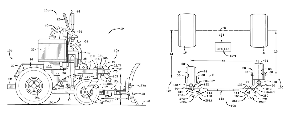
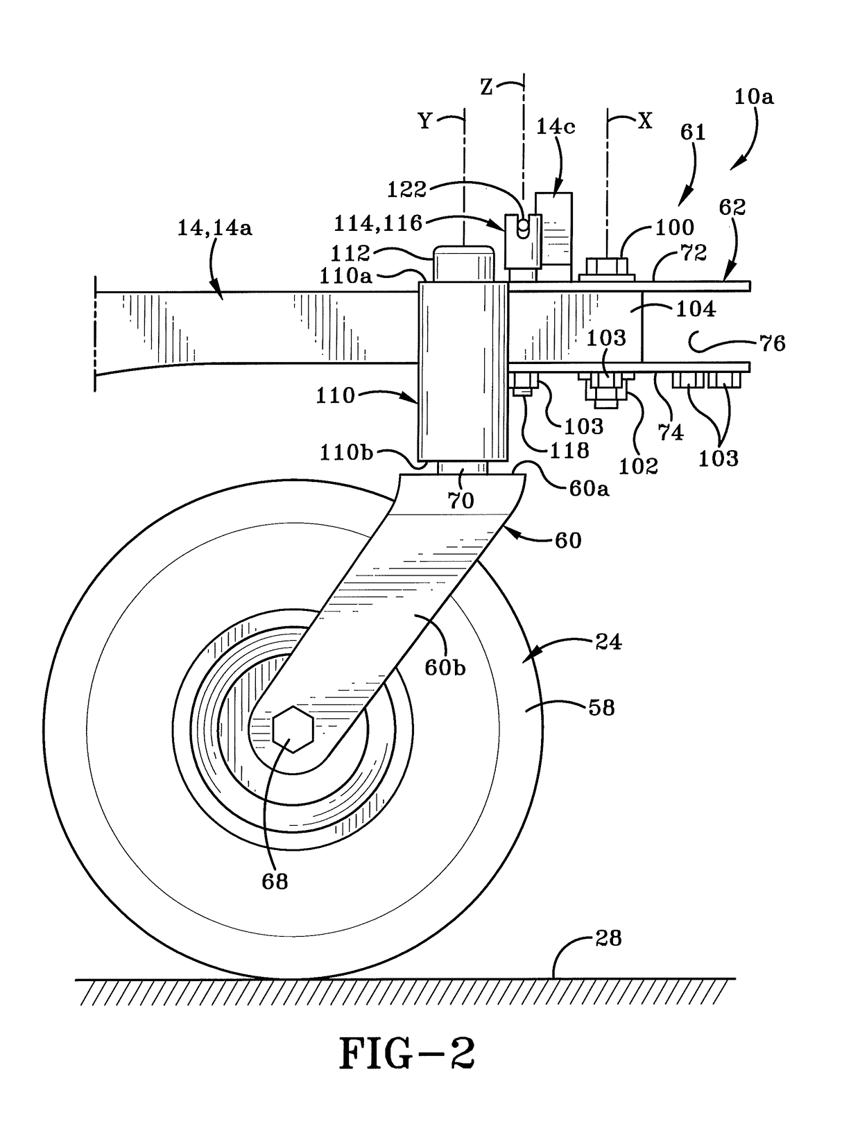
[0086]FIG. 6A shows the adjustment assembly, generally indicated at 161. All of the components of guide plate 62 are the same in adjustment assembly 161 but the configuration of the arm which secures guide plate 62 to yoke 60 is different. In particular, arm, represented by reference number 204, is a telescoping member that is adjustable in length to change the distance between guide plate 62 and wheel 58 and thereby further increase or decrease both the wheel base and wheel stance of vehicle 10. Arm 204 has a first end 204, with curved region 204b that is secured to bushing 98. The second end 204c of arm 204 is secured to sleeve 110.

[0087]When the above-described adjustments have been made to wheel assemblies 24, 26, wheels 58, 64 need to be placed back into engagement with ground surface 28. To that end, the operator will move joystick 44 in the opposite direction to arrow “A” (FIG. 8). This actuates the hydraulic system and causes piston 48 to be withdrawn, at least partially, in...

third embodiment

[0096]the adjustment mechanism is selectively operatively engaged with right front wheel assembly 24 and left front wheel assembly 26 to secure the same to vehicle frame 14. The adjustment mechanism includes an adjustment assembly 261A (FIG. 14) that engages right front wheel assembly 24 and an adjustment assembly 261B which engages left front wheel assembly 26. The adjustment mechanism also includes a pair of first arms 304 and a pair of second arms 305 that are selectively engageable with first and second adjustment assemblies 261A, 261B.

[0097]Adjustment assemblies 261A, 261B perform the same function as adjustment assembly 61 and in much the same manner but adjustment assemblies 261A, 261B are differently configured to adjustment assembly 61. Adjustment assembly 261A includes a guide plate 262A and adjustment assembly 261B includes a guide plate 262B. The structure of adjustment assembly 261A will be described in greater detail but it will be understood that the description appli...


PUM


Abstract

A utility vehicle with adjustable wheel assemblies to accommodate different weight attachments selectively engageable with the vehicle. Adjustment assemblies are provided to engage each of the front wheel assemblies. Each adjustment assembly includes a guide plate, a first arm of a first length and a second arm of a second length. The operator will select the appropriate one of the first and second arms to secure to the guide plate and to one of the front wheel assemblies. The guide plates include holes therein for locking the selected one of the arms in a particular orientation. This is accomplished by inserting a pin through an aperture in the selected first or second arm and one of the holes in the guide plate. A first end of the selected first or second arm is secured to the guide plate and a second end thereof is engaged with the associated wheel assembly.

Description

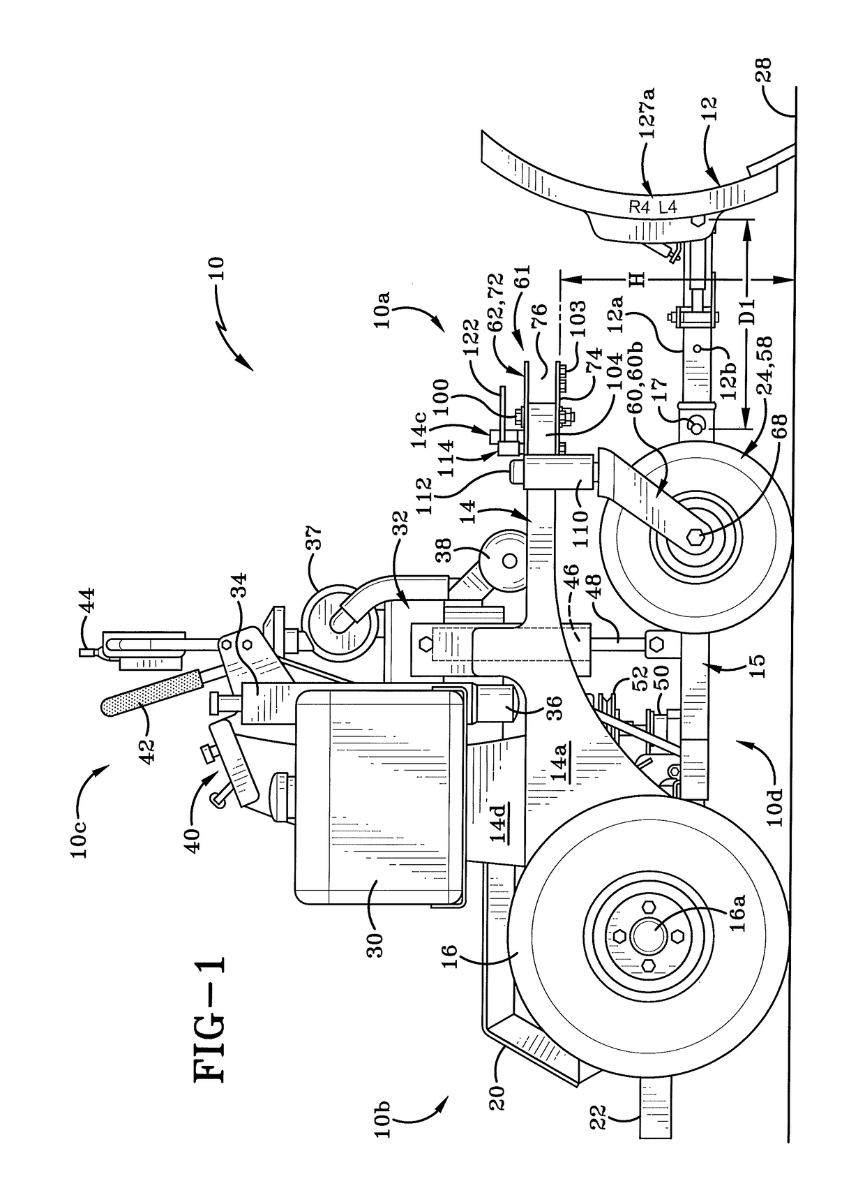
CROSS-REFERENCE TO RELATED APPLICATIONS[0001]This is a Continuation-in-Part of U.S. patent application Ser. No. 14 / 224,801, filed Mar. 25, 2014, the entire specification of which is incorporated herein by reference.BACKGROUND OF THE INVENTION[0002]Technical Field[0003]This invention relates generally to powered vehicles. More particularly this invention relates to a utility vehicle that is used for a variety of purposes by securing a range of different attachments to the vehicle. Specifically, this invention is directed to a utility vehicle that has adjustable front wheel assemblies that enable a user to change the wheel base (distance between the front and rear wheels) and the wheel stance (distance between the left wheels and the right wheels) so as to strike a balance of the overhung load, i.e., the load due to the weight of the attachment engaged with the vehicle, versus the weight of the rest of the vehicle and the operator relative to the performance of the attachment being en...

Claims


Application Information

Patent Timeline
Patent Type & Authority Patents(United States)
IPC IPC(8): B62D49/08B62D49/04B62D49/06
CPCB62D49/0678B62D49/04B62D49/0614A01D34/86A01D43/00A01D2101/00
Inventor PUGH, TODDHOPPEL, STEFFON
Owner GREEN IND INNOVATORS
Learn More