Casing float tool

a float tool and tool body technology, applied in the field of well casing sealing methods and apparatuses, can solve the problems of rupture discs, shattered rupture discs, and shearing of the securing mechanism, and achieve the effects of improving the breakability characteristics, and facilitating the shattered discs to suitably-sized pieces

Active Publication Date: 2017-03-14
NCS MULTISTAGE
View PDF10 Cites 40 Cited by
  • Summary
  • Abstract
  • Description
  • Claims
  • Application Information

AI Technical Summary

Benefits of technology

[0008]For example, the disc may be engaged within the casing string by a securing mechanism, which may be a shear ring. When freed from the constraints of the securing mechanism, the disc shatters against an impact surface within the casing string (e.g. a surface of a tubular). Hydraulic pressure does not cause rupture of the disc all by itself. Rather, hydraulic pressure causes disruption or shearing of the securing mechanism, such that the rupture disc is shattered by engagement against an impact surface within the casing string. The hydraulic pressure required to cause disruption of the securing mechanism is less than the hydraulic pressure that would normally be required to break the rupture disc. The engagement of the disc against the impact surface (the disc being impelled against the impact surface) allows the disc to rupture at lower pressure than would generally be required if hydraulic pressure alone was the sole mechanism for rupturing the disc, thereby allowing less hydraulic pressure to be required for the disc to be ruptured. Also, as will be described below, this allows the disc to be broken into suitably-sized pieces that will not affect wellbore equipment such as float devices.
[0009]There is no need to send weights, sharp objects or other devices (e.g. drop bars or sinker bars) down the casing string to break the rupture disc. Nor is there a need for complicated tubular arrangements, such as sliding sleeves to break the rupture disc. Such sleeves do not tend to break the disc into sufficiently small pieces. In the present arrangement, the rupture disc and rupture disc assembly can be so arranged that the rupture disc gets broken in sufficiently small pieces that the disc pieces can be removed by fluid circulation, without damaging the casing string. In addition, full casing ID (inside diameter) is restored after the rupture disc is broken, so that there is no need to drill out any part of the device. This full casing ID is useful for use in ball-drop systems. Once the disc has ruptured, normal operations, such as cementing, may be performed. The device is straight-forward to install, avoids the cost and complexity of many known casing flotation methods and devices, and decreases completion time.
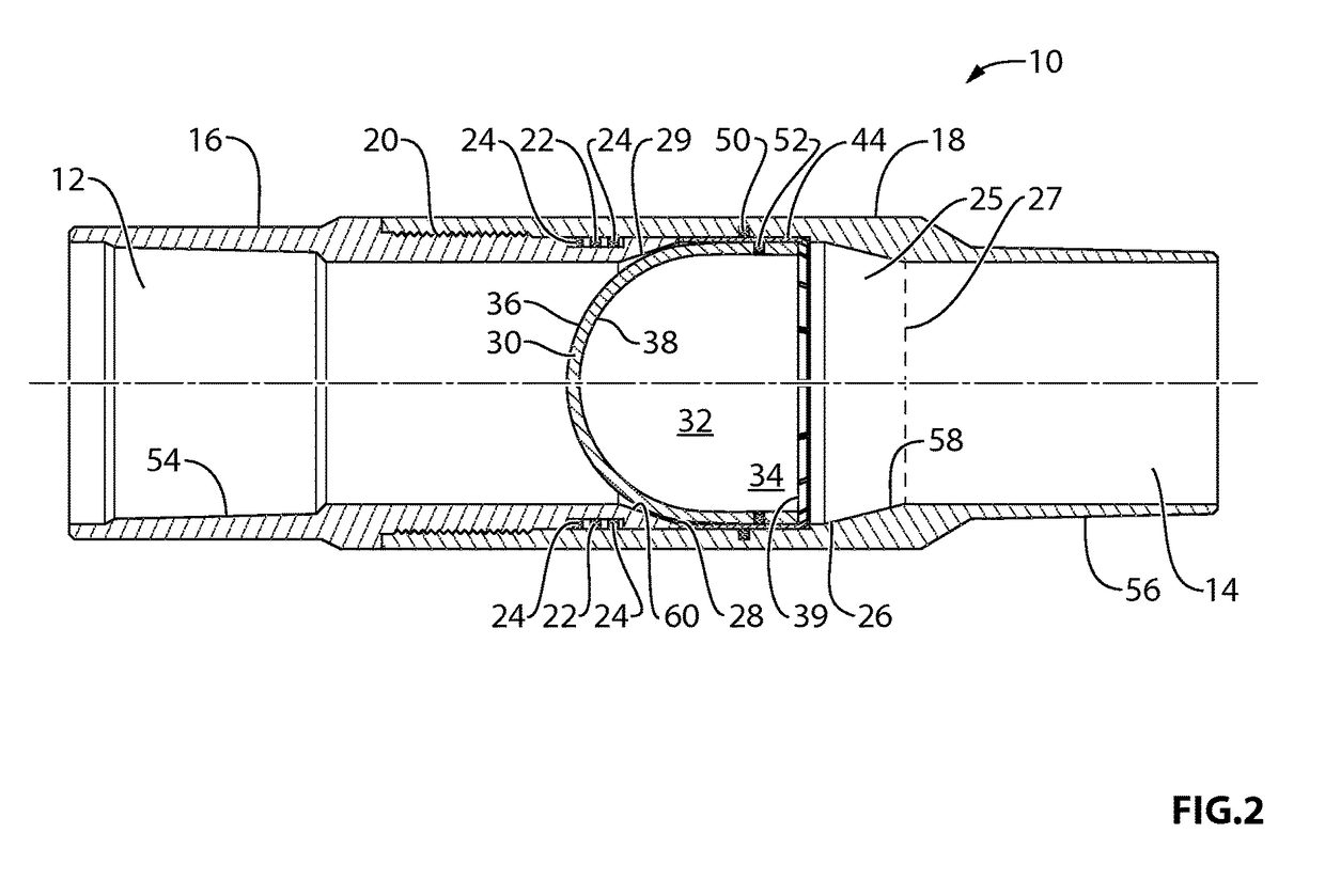
[0011]In one embodiment, the securing mechanism generally provides a convenient means to fluidically seal the rupture disc within the casing string, and essentially, to facilitate rupturing of the disc, by the mechanisms described herein. In one example, the securing mechanism is a shear ring, the shear ring having a continuous side surface and a circumferential aperture. The lower circumferential edge of the shear ring includes a plurality of tabs inwardly extending into the aperture. Generally, the threshold shearing pressure of the tabs is less than the rupture burst pressure of the disc (e.g. the pressure at which hydraulic pressure alone causes rupture of the disc), so that the tabs are sheared before the disc is shattered. The shearing allows sudden or rapid free movement of the disc in the direction of the lower tubular member, so that the disc can be shattered by impact.
[0012]It is desirable for the rupture disc to be shattered into sufficiently small pieces that the shattered pieces do not damage the casing string, and so that the pieces do not clog equipment (such as the float shoe) within the casing string. To accomplish this, various configurations of the rupture disc may be employed. For example, the rupture disc may have a pattern of grooves etched on the outer surface of the dome, the grooves providing lines of weakness to facilitate breakage of the disc into suitably-sized pieces. The thickness of the rupture disc may also be such as to improve the breakability characteristics. The small size of the pieces allow the rupture disc assembly to be used with ball-drop systems (typically, the smallest ball drop is less than one inch).

Problems solved by technology

Rather, hydraulic pressure causes disruption or shearing of the securing mechanism, such that the rupture disc is shattered by engagement against an impact surface within the casing string.
Such sleeves do not tend to break the disc into sufficiently small pieces.

Method used


Image

  • Casing float tool
  • Casing float tool
  • Casing float tool

Examples


examples

Weight Reduction

[0068]In certain examples, a 54% reduction in lateral casing weight was achieved using the float tool of the present invention. In one particular example, the casing weight in air was 17.3 kg / m (11.9 lb / ft). The casing weight in water was 15.1. kg / m (10.4 lb / ft). The effective casing weight using the float tool of the present invention was 6.9 kg / m (4.8 lb / ft).

[0069]Sample Calculations:

[0070]An example calculation of surface pressure is presented. The well true vertical depth is 1,500 m (4,920 ft). The fluid density is 1,050 kg / m3. The bottom hole pressure is 15.4 MPa (2240 psi). The minimum rupture burst pressure rating is therefore 2240 psi+500 psi=2740 psi. The rupture burst pressure of the assembly is 3000 psi. The surface pressure is calculated as Surface Pressure=Rupture Burst Pressure Rating less Bottom Hole Hydrostatic Pressure. In the present case, 3000 psi less 2240 psi=860 psi (5.93 MPa). In another example, if the differential pressure inside the tubing i...


PUM


Abstract

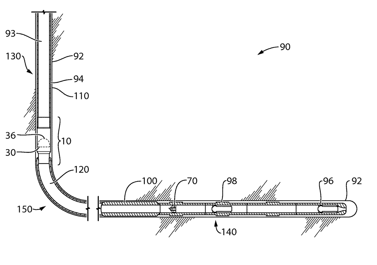
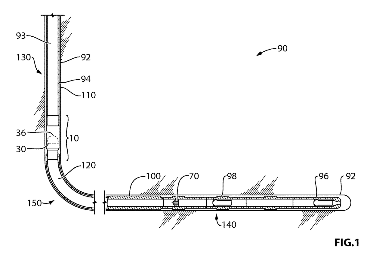
A rupture disc assembly and a float tool incorporating the rupture disc assembly is disclosed. The rupture disc assembly may include a rupture disc assembly comprising a rupture disc, an upper tubular portion and a lower tubular portion, and a securing mechanism for holding the rupture disc between the upper and lower tubular portions. A float tool for creating a buoyant chamber in a casing string may include the rupture disc assembly and a sealing device for sealing the lower end of the casing string, the buoyant, sealed chamber may be created there between. In operation, applied fluid pressure causes the rupture disc to move downward. The rupture disc may be shattered by contact with a surface on the lower tubular portion. Full casing internal diameter may be restored in the region where the rupture disc formerly sealed the casing.

Description

CROSS-REFERENCE SECTION TO RELATED APPLICATIONS[0001]This application claims the benefit of U.S. Provisional Application No. 61 / 761,070 filed on Feb. 5, 2013, the disclosure of which is hereby incorporated by reference in its entirety.FIELD OF THE INVENTION[0002]This invention relates to a method and apparatus for sealing well casings.BACKGROUND[0003]In many wells, it may be difficult to run the casing to great depths because friction between the wellbore and the casing often results in a substantial amount of drag. This is particularly true in horizontal and / or deviated wells. In some cases, the drag on the casing can exceed the available weight in the vertical section of the wellbore. If there is insufficient weight in the vertical portion of the wellbore, it may be difficult or impossible to overcome drag in the wellbore.[0004]Various attempts have been made to overcome this drag and achieve greater well depths and / or to achieve a horizontal well. For example, techniques to alter...

Claims


Application Information

Patent Timeline
Patent Type & Authority Patents(United States)
IPC IPC(8): E21B17/08E21B34/06E21B33/14E21B21/10
CPCE21B17/08E21B21/10E21B33/14E21B34/063E21B7/20E21B17/14E21B33/146
Inventor GETZLAF, DONALDSTROMQUIST, MARTYRAVENSBERGEN, JOHNDEVLIN, DAVIDBRADEN, DOULGASHARRIS, TRAVIS
Owner NCS MULTISTAGE
Why Eureka
Try Eureka