Damping arrangement for dissipating oscillating energy of an element in a system, more particularly in a microlithographic projection exposure apparatus

a technology of oscillating energy and damping arrangement, which is applied in the direction of shock absorbers, photomechanical devices, instruments, etc., can solve the problems of mechanical disturbance, excessive increase, and disadvantageous effect on the positional stability of optical components, so as to optimize the damping degree of the system

Active Publication Date: 2017-03-14
CARL ZEISS SMT GMBH
View PDF30 Cites 4 Cited by
  • Summary
  • Abstract
  • Description
  • Claims
  • Application Information

AI Technical Summary

Benefits of technology

[0014]It is an object of the present invention to provide a damping arrangement for dissipating oscillation energy of an element in a system, more particularly in a microlithographic projection exposure apparatus, which enables effective and temporally stable damping.
[0024]At the same time, the introduction of additional significant stiffnesses can be avoided in this case, such that it is also possible to take account of the requirements in respect of ever lower natural frequencies in the system and also of sufficient temporal stability of the damping effect achieved.
[0035]In further embodiments, however, the magnet can also be fixedly linked to the relevant element, wherein the absorber mass is produced from a nonmagnetic material. Such a configuration has the advantage, in particular, that an arrangement of a plurality of oscillation absorbers constructed in the above-described manner according to the invention alongside one another can be realized without an undesirable relative movement of the magnets that are adjacent in such an arrangement taking place. Furthermore, owing to the fixing of the magnets, there is the possibility of providing magnet termination elements (e.g. in the form of iron plates or the like) for suppressing magnetic leakage fields in conjunction with the damping arrangement according to the invention, without an undesirable relative movement between such magnet termination elements and the magnets through to a mechanical short circuit taking place.
[0044]The degree of damping of the mass-spring system (m2, k2) formed by the auxiliary mass m2 increases from the upper to the lower row of diagrams from FIG. 7b, namely from a low value ζ2=0.01 for the diagrams of the upper row to a value ζ2=10 for the diagrams of the lower row in FIG. 7b. As can likewise be discerned, an increase in the damping of the mass-spring system (m2, k2) formed by the auxiliary mass m2 leads to a decrease in the two “side peaks” present initially (i.e. in the case of low damping) in the vicinity of the resonant frequency of the mass-spring system (m1, k1), but a further increase in the damping leads again to a more highly pronounced peak or a more pronounced sharpness of resonance. A—relative to the optimum value—lower value (upper row in FIG. 7b, ζ2=0.01) or higher value (lower row in FIG. 7b, ζ2=10) of the degree of damping ζ2 of the mass-spring system (m2, k2) formed by the auxiliary mass m2 leads to a lower damping efficiency. The last-mentioned effect can be explained by the fact that, in the case of an excessively high degree of damping of the mass-spring system (m2, k2) formed by the auxiliary mass m2, the energy dissipation is suppressed since practically no movement bringing about the energy dissipation takes place any longer.
[0045]As is furthermore evident from a comparison of the diagrams from FIG. 7, with suitable choice of the damping it is possible to obtain high robustness with regard to a frequency detuning of the auxiliary or absorber mass (that is to say an effective damping even over a wide frequency spectrum). In particular, the middle row in FIG. 7b shows that a well-damped system for all frequency values f2 examined is obtained by increasing the degree of damping ζ2 to a value of approximately ζ2≈0.3.

Problems solved by technology

Mechanical disturbances caused by vibrations always have a disadvantageous effect on the positional stability of the optical components.
Weakly damped mechanical resonances in the system lead, in the range of resonant frequencies, to a local excessive increase in the disturbance spectrum and to an associated impairment of the positional stability of passively mounted components and also of actively controlled components.
Furthermore, resonances in the case of controlled systems can lead to instability of the control loop.
Possible measures for eliminating the control instability caused by mechanical resonances, such as, for instance, reducing the control bandwidth or introducing local suppression filters (so-called “notch filter”), depending on the situation, have a disadvantageous to dramatic effect on the control performance and on the associated positional stability of the controlled optical element.
In the worst case, the system can no longer be controlled stably at all.
Consequently, oscillations that occur lead to growing problems with regard to the performance of the system and also to the effect that active position control as described initially can no longer be operated stably.
With regard to the required vacuum resistance, however, the choice of suitable materials for the damping element with sufficient intrinsic damping is limited in an EUV projection exposure apparatus.
Further problems can result from the fact that the stiffness properties and also the damping properties of the materials can change over time.
Even though the damping via an absorber mass is advantageous particularly in situations in which e.g. mechanical linking to a reference system as in FIG. 8a via dampers is not possible, with available materials such as fluoroelastomers, for example, the problem can still occur that these have, in addition to the desired damping effect, an undesirably high parasitic intrinsic stiffness which, moreover, can vary temporally over the lifetime of the system or else when there are changes in the atmosphere, and so as a result, besides the desirable damping effect, changes in the resonant frequency of the damping arrangement can also arise with the consequence that the abovementioned required tuning to the resonant frequency of the element to be damped or of the associated mass-spring system is no longer provided.

Method used


Image

  • Damping arrangement for dissipating oscillating energy of an element in a system, more particularly in a microlithographic projection exposure apparatus
  • Damping arrangement for dissipating oscillating energy of an element in a system, more particularly in a microlithographic projection exposure apparatus
  • Damping arrangement for dissipating oscillating energy of an element in a system, more particularly in a microlithographic projection exposure apparatus

Examples


Embodiment Construction

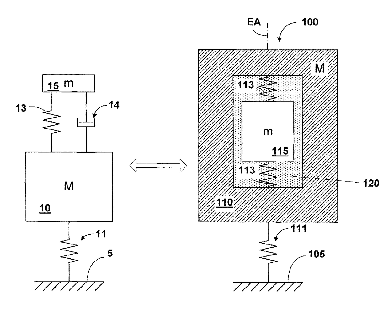
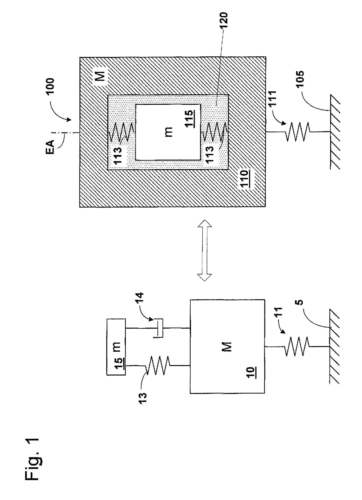
[0057]Firstly, a damping arrangement in accordance with a first embodiment of the disclosure is explained below with reference to FIG. 1. The damping arrangement according to the disclosure is illustrated in the right-hand part of FIG. 1, whereas that is contrasted with a conventional damping arrangement using an oscillation absorber in the left-hand part of FIG. 1 for comparison purposes.

[0058]The damping arrangement 100 according to FIG. 1 serves for dissipating oscillation energy of an element 110 in a system, more particularly in a microlithographic projection exposure apparatus. The element 110 can be, for example, an optical element (more particularly a mirror), an actuator component of an actuator serving for actuating such an optical element, an articulated element, a reaction or filter mass or an arbitrary structural element, for example a carrying frame or a measurement frame.

[0059]In the exemplary embodiment (and without the invention being restricted thereto) the element...


PUM

PropertyMeasurementUnit
operating wavelengthaaaaaaaaaa
wavelengthaaaaaaaaaa

Abstract

The invention relates to a damping arrangement for dissipating oscillation energy of an element in a system, more particularly in a microlithographic projection exposure apparatus, comprising an absorber mass, which is mounted via a stable mounting with respect to the element, wherein the absorber mass is arranged in a cavity present within the element and is at least partly surrounded by a fluid situated in the cavity, wherein a mass-spring system is formed by the absorber mass, the system damping a translational movement component of an oscillation of the element that exists at the linking point of the absorber mass, and wherein the stable mounting is formed by a rheological fluid that is electrically controllable or controllable via electric or magnetic fields.

Description

CROSS REFERENCE TO RELATED APPLICATIONS[0001]The present application is a continuation of, and claims priority under 35 USC 120 to, international application PCT / EP2012 / 064857, filed Jul. 30, 2012, which claims priority under 35 USC 119 to German Patent Application DE 10 2011 080 318.1 and priority under 35 USC 119e to U.S. 61 / 514,550, both filed on Aug. 3, 2011. The content of these applications is hereby incorporated by reference.BACKGROUND OF THE INVENTION[0002]Field of the Invention[0003]The invention relates to a damping arrangement for dissipating oscillating energy of an element in a system, more particularly in a microlithographic projection exposure apparatus.[0004]Prior Art[0005]Microlithography is used for producing microstructured components, such as, for example, integrated circuits or LCDs. The microlithography process is carried out in a so-called projection exposure apparatus comprising an illumination device and a projection lens. The image of a mask (=reticle) illu...

Claims


Application Information

Patent Timeline
Patent Type & Authority Patents(United States)
IPC IPC(8): F16F15/03F16F7/10G03F7/20
CPCF16F7/1011G03F7/709
Inventor HAUF, MARKUS
Owner CARL ZEISS SMT GMBH
Why Eureka
Try Eureka