Receiver system for a fresnel solar plant

a solar plant and receiver technology, applied in the direction of solar heat collector mounting/support, solar heat collector safety, light and heating apparatus, etc., to achieve the effect of higher yield

Active Publication Date: 2017-03-28
RIOGLASS SOLAR HLDG SA
View PDF26 Cites 4 Cited by
  • Summary
  • Abstract
  • Description
  • Claims
  • Application Information

AI Technical Summary

Benefits of technology

[0009]The object of the invention is to configure the solar plant by an improved construction to be less sensitive to temperature fluctuations and environmental influences and thus finally also to increase its efficiency and service life.
[0046]Alternatively or additionally, for this purpose, the sleeve tube is tapered, preferably at least on a central longitudinal segment. This measure also serves for reducing the gap between the absorber tube and the sleeve tube, so that the mirror array can be arranged at a short distance to the absorber tube.

Problems solved by technology

However, the mirrors also expand to a significant extent due to the heating, but this expansion is different than that of the absorber tube.

Method used


Image

  • Receiver system for a fresnel solar plant
  • Receiver system for a fresnel solar plant
  • Receiver system for a fresnel solar plant

Examples


first embodiment

[0080]FIG. 9 shows, in a schematically very simplified form, the optical components of the receiver system according to the invention according to a The receiver tube 906 having an absorber tube 908 and a sleeve tube 910, which surrounds the absorber tube 908 concentrically, can be seen therein. Also counted among the optical components is the mirror array 912 above the receiver tube 906, which is separated in the longitudinal direction into the two first and second mirror elements 932 and 934 with a gap 936 lying in between, directly over the receiver tube 906, which is closed optically at least partially by a mirror segment 968. Closed optically at least partially in this case means that, considered in cross section, an air gap 970 remains between the first mirror element 932 and the mirror segment 968 as well as between the second mirror element 934 and the mirror segment 968. Both air gaps 970 provide sufficient ventilation openings in the region of the two apical points of the...

third embodiment

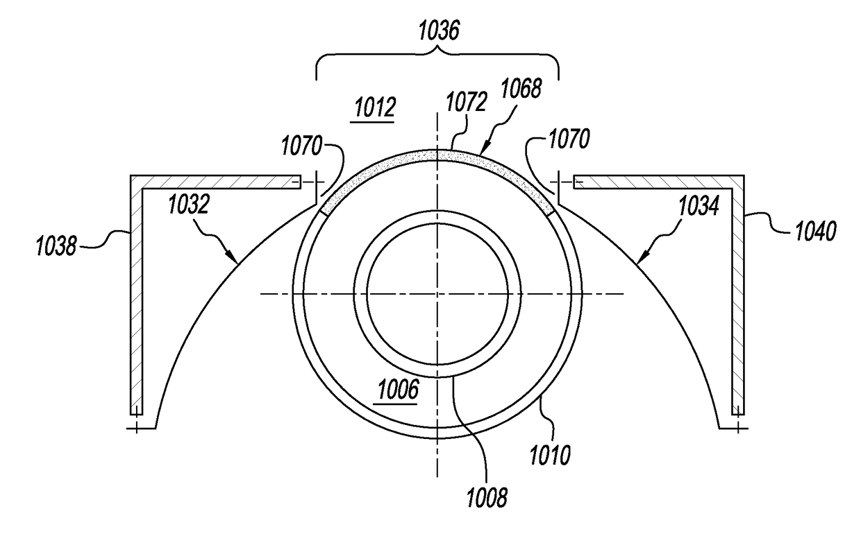
[0086]the optical components of the receiver system according to the invention is shown schematically in FIG. 11. With respect to the mirror array 1112, this essentially corresponds to the embodiment of FIG. 9. As it was therein, the mirror array is composed of a first, a second, and a third mirror element 1132, 1134, and 1171.

[0087]A difference from the example of embodiment in FIG. 9 consists of a modified shape of the receiver tube 1106, in which the absorber tube 1108 is disposed eccentrically in the sleeve tube 1110. Stated more precisely, the absorber tube 1108 is shifted up, so that the gap between the lateral surface of the absorber tube 1108 and the lateral surface of the sleeve tube 1110 is reduced on the upper side facing the third mirror element 1171. In this way, radiation losses are minimized; see also FIG. 12A.

[0088]In addition, a first profile element 1138, which is associated with the first mirror element 1132; a second profile element 1140, which is associated with...


PUM


Abstract

A receiver system for a Fresnel solar plant is provided. The system includes an absorber tube defining a longitudinal direction and a mirror array that runs parallel to the longitudinal direction. The mirror array has a mirror-symmetrical curve profile having at least one top apex for concentrating light beams onto the absorber tube. The mirror array has ventilation holes in the region of the apex.

Description

CROSS REFERENCE TO RELATED APPLICATIONS[0001]This application is a continuation of International Application Serial No. PCT / EP2012 / 074906 filed Dec. 10, 2013, now pending, which claims benefit under 35 U.S.C. §119(a) of German Patent Application No. 10 2011 088 830.6, filed Dec. 16, 2011, the entire contents of both of which are incorporated herein by reference.BACKGROUND OF THE INVENTION[0002]1. Field of the Invention[0003]The invention relates to a receiver system for a Fresnel solar plant having an absorber tube defining a longitudinal direction, a mirror array parallel to the longitudinal direction as a secondary concentrator, which has, crosswise thereto, a mirror-symmetrical curve profile having at least one apical point lying on top for concentrating light beams onto the absorber tube.[0004]2. Description of Related Art[0005]The generic receiver system is part of a solar power plant, which has, in addition, a primary concentrator in the form of a field of rows of mirrors moun...

Claims


Application Information

Patent Timeline
Patent Type & Authority Patents(United States)
IPC IPC(8): F24J2/10F24J2/05F24J2/04F24J2/18F24J2/46F24J2/16F24J2/52F24J2/14F24S10/40F24S23/70F24S23/74F24S23/77F24S23/79
CPCF24J2/10F24J2/0488F24J2/055F24J2/1047F24J2/14F24J2/16F24J2/18F24J2/4625F24J2/4636F24J2/5232F24J2002/1004F24J2002/108F24J2002/109F24J2002/1023Y02E10/44Y02E10/45Y02E10/47F24S10/45F24S23/80F24S23/74F24S23/77F24S23/79F24S40/55F24S40/80F24S25/12F24S2023/834F24S2023/872F24S2023/876F24S70/60F24S23/70F24S2023/83Y02E10/40
Inventor SAUERBORN, ANDREASGNAEDIG, TIMKUCKELKORN, THOMASBRENGELMANN, TIM
Owner RIOGLASS SOLAR HLDG SA
Why Eureka
Try Eureka