Slotline antenna
a technology of slotline antennas and antennas, applied in the direction of antennas, instruments, electrical equipment, etc., can solve the problems of unbalanced feeding of cables, poor reflection coefficient of electrically short antennas at feeding ports, etc., to reduce the dispersion of antennas, reduce the effect of unnecessary circuit board area, and reduce the ratio of signal power propagating in the surrounding air to the signal power propagating in the circuit board
- Summary
- Abstract
- Description
- Claims
- Application Information
AI Technical Summary
Benefits of technology
Problems solved by technology
Method used
Image
Examples
first embodiment
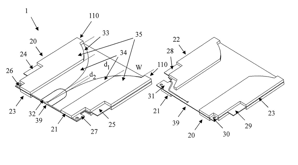
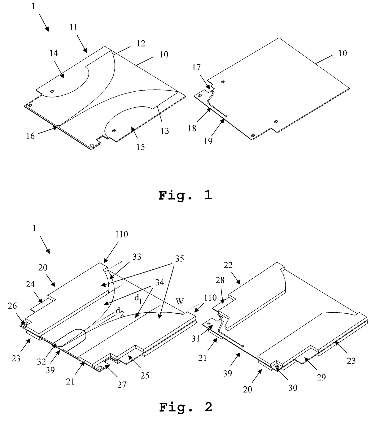
[0032]FIG. 1 shows a first embodiment of the inventive antenna 1. In FIG. 1, for reasons of clarity and comprehensibility, not all components of the antenna have been depicted. In FIG. 2, a view of the antenna showing all components is depicted. On the left side of the FIG. 1, a front-view of the antenna 1 is shown. On the right side, a back-view of the antenna 1 is shown.
[0033]The antenna 1 comprises a circuit board 10 and two antenna elements 12, 13 formed in a metallization layer 11 on the front side of the circuit board 10. The antenna elements 12, 13 are not connected electrically. The antenna element 13 is directly connected to a connector 17, while the antenna element 12 is connected to the connector 17 through a wire 19 and a feed line 18. The connector 17 is for example a coaxial connector. The antenna element 13 in this case is connected to the shielding of the coaxial connector, while the antenna element 12 is connected to the center line of the coaxial connector 17.
[0034...
second embodiment
[0045]In FIG. 6, a second embodiment of the inventive antenna is shown. In this embodiment, the antenna 2 does not necessarily comprise absorber elements. The circuit board 70 of the antenna 2 here furthermore comprises a recess 72 at the emitting side of the antenna 2. The shape of the circuit board 70 follows the shape of emitting edges 71 of the antenna elements. The circuit board 72 though extends beyond the shape of the antenna elements into the emitting direction of the antenna slightly. A current flowing in the antenna elements at the emitting edge of the antenna elements results in an electromagnetic field along the emitting edge of the antenna elements being present in the surround air and in the circuit board dielectric. These two media have different electrical permittivity creating dispersion effect. The cut 72 reduces the dispersion and increase radiation directivity.
[0046]Moreover, in FIG. 7, the absolute gain 111 of an embodiment as shown in FIG. 6 is depicted. Gain d...
third embodiment
[0048]In FIG. 8, a third embodiment of an inventive antenna 83 is shown. The antenna 83 is part of an antenna system 3 which is comprised by the antenna 83, a base plate 80, on which the antenna 83 is mounted perpendicularly, an absorber base 81 mounted on the base plate 80 and a plurality of absorbers mounted on the absorber base 81. The absorbers 82 extend from a non-emitting side of the antenna towards the emitting side of the antenna 83 and are mounted parallel to the antenna. The absorbers advantageously are shorter than the antenna 83. The antenna 83 is an antenna according to one of the previously shown embodiments of the inventive antenna.
PUM
 Abstract
Description
Claims
Application Information
 - R&D
- Intellectual Property
- Life Sciences
- Materials
- Tech Scout
- Unparalleled Data Quality
- Higher Quality Content
- 60% Fewer Hallucinations
Browse by: Latest US Patents, China's latest patents, Technical Efficacy Thesaurus, Application Domain, Technology Topic, Popular Technical Reports.
© 2025 PatSnap. All rights reserved.Legal|Privacy policy|Modern Slavery Act Transparency Statement|Sitemap|About US| Contact US: help@patsnap.com


