Delay lock loop

Active Publication Date: 2017-03-28
VIA ALLIANCE SEMICON CO LTD
View PDF2 Cites 0 Cited by
  • Summary
  • Abstract
  • Description
  • Claims
  • Application Information

AI Technical Summary

Benefits of technology

[0007]The delay lock loop of the invention eliminates an initial delay of the delay unit to provide a perfect delay purpose, wherein the delay unit is not capable of eliminating the initial delay. Compare to a conventional delay lock loop, the elements utilized b

Problems solved by technology

However, the clock signal is easily affected by the manufacturing process o

Method used


Image

  • Delay lock loop
  • Delay lock loop
  • Delay lock loop

Examples


Example

[0026]The following description is of the best-contemplated mode of carrying out the invention. This description is made for the purpose of illustrating the general principles of the invention and should not be taken in a limiting sense. The scope of the invention is best determined by reference to the appended claims.

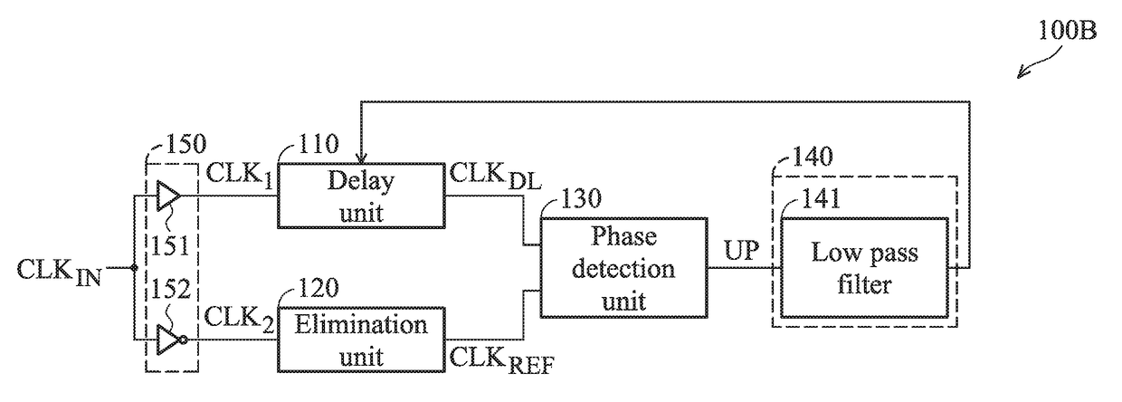
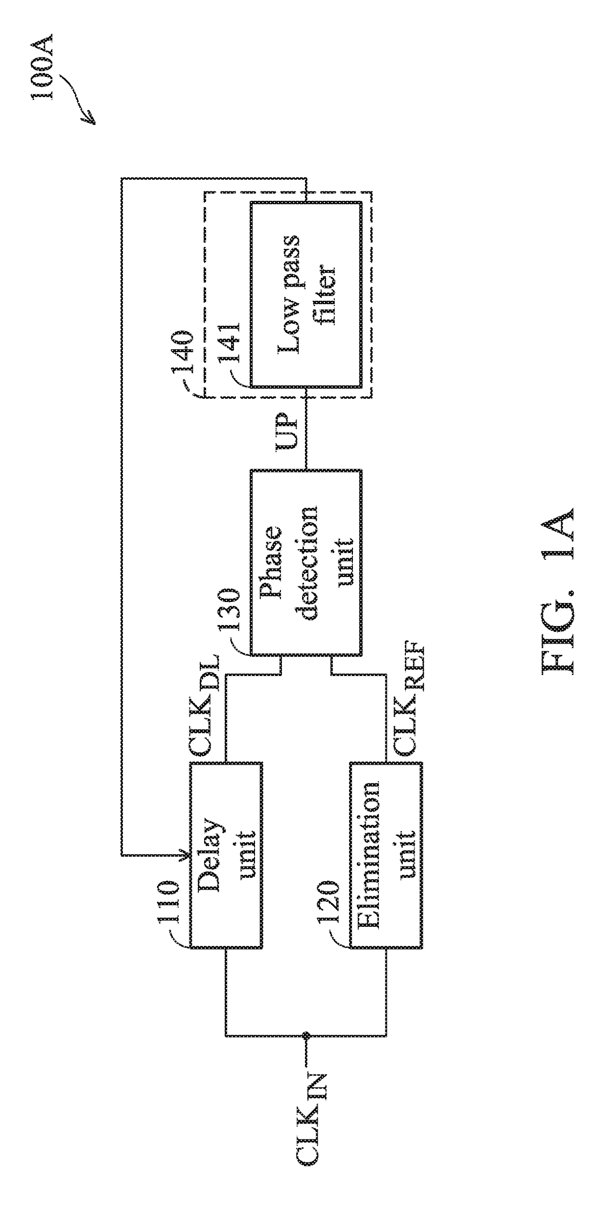
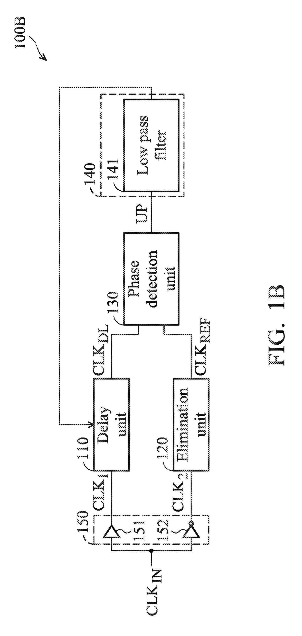
[0027]FIG. 1A is a schematic diagram of an exemplary embodiment of a delay lock loop, according to various aspects of the present disclosure. The delay lock loop 100A comprises a delay unit 110, an elimination unit 120, a phase detection unit 130 and a control unit 140. The delay unit 110 has a delay factor and delays a first clock signal to generate a second clock signal according to the delay factor. In this embodiment, the delay unit 110 delays an input clock signal CLKIN to generate a clock signal CLKDL. The invention does not limit the internal circuit structure of the delay unit 110. Any circuit can serve as a delay unit 110, as long as the circuit is capable of ...


PUM


Abstract

A delay lock loop including a selection unit, a delay unit, and a phase detection unit is provided. The selection unit receives a non-inverted clock signal and an inverted clock signal and generates a first clock signal and a second clock signal according to an indication signal. The delay unit is coupled to the selection unit. The delay unit includes a delay factor and delays the first clock signal to generate a third clock signal according to the delay factor. The phase detection unit is coupled to the delay unit and the selection unit and generates the indication signal according to a phase difference between the second and third clock signals. The delay unit adjusts the delay factor according to the indication signal.

Description

CROSS REFERENCE TO RELATED APPLICATIONS[0001]This Application claims priority of China Patent Application No. 201510875427.0, filed on Dec. 2, 2015, the entirety of which is incorporated by reference herein.BACKGROUND OF THE INVENTION[0002]Field of the Invention[0003]The invention relates to an electronic circuit, and more particularly to a delay lock loop.[0004]Description of the Related Art[0005]As technological developments have progressed, the number of circuits integrated into a single integrated circuit (IC) have increased. Each of circuits integrated into a single IC operates according to a clock signal. However, the clock signal is easily affected by the manufacturing process or temperature. When the clock signal is shifted, the IC cannot work normally.BRIEF SUMMARY OF THE INVENTION[0006]In accordance with an embodiment, a delay lock loop comprises a selection unit, a delay unit, and a phase detection unit. The selection unit receives a non-inverted clock signal and an inver...

Claims


Application Information

Patent Timeline
IPC IPC(8): H03L7/08H03L7/085H03K5/134H03K5/00
CPCH03L7/085H03K5/134H03K2005/00019H03L7/0805H03L7/0812H03L1/02
Inventor SI, QIANGJIANG, FAN
Owner VIA ALLIANCE SEMICON CO LTD
Why Eureka
Try Eureka