

MIMO communication system for propagation environment including deterministic communication channel, and antennas for MIMO communication system
a communication system and propagation environment technology, applied in the field of space division multiplexing system, can solve the problems of serious phase rotation, impede the realization of high-quality communication, and difficult to ensure the aforesaid definitive communication channel matrix, and achieve the effect of reducing the spacing between antennas
Active Publication Date: 2017-03-28
NEC CORP
View PDF8 Cites 23 Cited by
- Summary
- Abstract
- Description
- Claims
- Application Information
AI Technical Summary
Benefits of technology
This approach enables the formation of line-of-sight orthogonal channels with reduced antenna spacing, enhancing communication channel capacity and convenience by compensating for phase fluctuations caused by environmental factors, such as wind and temperature, without requiring extensive feedback or additional links.
Problems solved by technology
However, the communication system adopting the MIMO has been centered on a mobile communication, but has not been applied for a fixed communication to date.
Thus, it is rich scattering resulting from such fact that always hinders a high-quality communication from being realized.
Accordingly, the movement of the antennas orientation whose sensitivity is high against such subtle climate conditions as the wind, the surrounding temperature and so forth causes a serious phase rotation.
Under such conditions, it is hard to ensure the aforesaid definitive communication channel matrix.
However, such feedback data not only increases overheads, but also requires reverse links.
In particular, such singular states are analytically bothersome, by which there are some cases where the serious transition of such singular vectors might arise.
Further, as one of the big problems with the deterministic line-of-sight MIMO communication system, it requires that carrier synchronization be made between antennas at the transmitting side or the receiving side according to the aforesaid conventional method.
In other words, the problem with the carrier synchronization among the antennas becomes large constraint to construct the fixed microwaves communication system.
Method used
View moreImage
Smart ImageViewing Examples

Examples
example
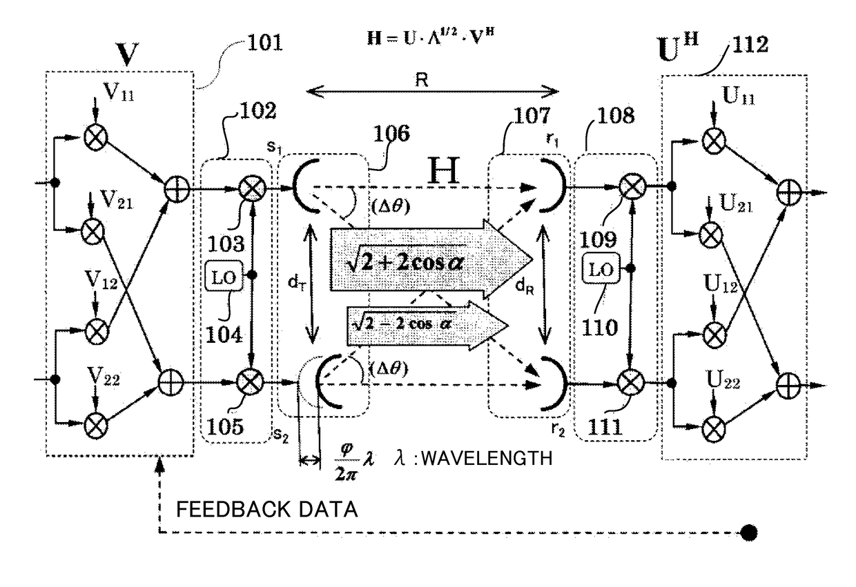
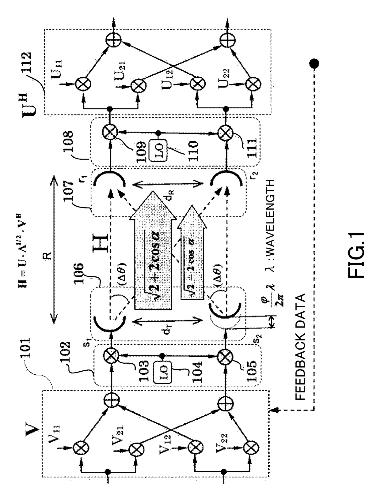
[0401]As a simple example, the above formula is applied to the arrangement with two antennas.
As the fixed arbitrary transmission matrix, for instance, the following formula 124 is selected.
[0402]V=[-1212-12-12]{Formula124}
[0403]Based on the following formula 125, the following formula 126 is established.
[0404]H0=[1-j-j1]{Formula125}UH=VHN·TH·HoH·WH=[-12-1212-12]·[100ⅇ-jΦ1]·[1jj1]·[100ⅇ-jϕ1]=[-1-jⅇ-jΦ12-jⅇ-jϕ1-jⅇ-j(Φ1+ϕ1)21-jⅇ-jΦ12jⅇ-jϕ1-jⅇ-j(Φ1+ϕ1)2]{Formula126}
[0405]Hereafter, the orthogonal relation adopted in the above formula 114 is explained as follows.
Login to View More PUM
 Abstract
In a MIMO communication system that includes a transmitter and a receiver and forms line-of-sight orthogonal channels between the transmitter-side transmitting antenna and the receiver-side receiving antenna, the MIMO communication system is provided between the transmitting antenna and the receiving antenna with an optimum antenna-to-antenna spacing shortening unit to shorten an optimum antenna-to-antenna spacing by changing the phase rotation of a carrier wave used for directly opposed waves between opposed antennas, and the phase rotation of a carrier wave used for intersecting waves between oblique antennas in such a manner that the amount by which one of the phase rotations changes is different from that by which the other phase rotation changes.
Description
[0001]This application is a National Stage Entry of PCT / JP2014 / 064213 filed on May 29, 2014, which claims priority from Japanese Patent Application 2013-114036 filed on May 30, 2013, the contents of all of which are incorporated herein by reference, in their entirety.TECHNICAL FIELD[0002]The present invention relates to a space division multiplexing system (hereinafter, referred to as MIMO; Multiple-Input / Multiple-Output), particularly, pertaining to an MIMO communication system adopted for a fixed microwaves communication system in the line-of-sight communication system, a mobile communication system in which the line-of-sight propagation is included even under the propagation environment entailing reflections and scatterings and the propagation environment in which the line-of-sight propagation is included indoor and to antennas for such MIMO communication system.BACKGROUND ART[0003]In the wireless communication, the communication system adopting such MIMO has prevailed over the r...
Claims
Login to View More Application Information
Patent Timeline
 Patent Type & AuthorityPatents(United States)
IPC IPC(8): H03H7/40H04B7/0456H04L5/00
CPCH04B7/0456H04L5/0048
InventorMARU, TSUGUO
OwnerNEC CORP