Brake control apparatus

a technology of brake control and control unit, which is applied in the direction of fluid braking transmission, braking system, vehicle components, etc., can solve the problems of poor and the expansion of the brake control apparatus, so as to improve the heat radiation performance and vibration resistance of the control unit

Active Publication Date: 2017-04-04
HITACHI ASTEMO LTD
View PDF16 Cites 2 Cited by
  • Summary
  • Abstract
  • Description
  • Claims
  • Application Information

AI Technical Summary

Benefits of technology

[0003]The present invention has been made in view of the above problems. It is accordingly an object of the present invention to provide a brake control apparatus with an electric motor and a control unit so as to, while being downsized, improve the heat radiation performance and vibration resistance of the control unit.
[0005]In the present invention, the heat radiating seat is located on the side of the housing at the position apart from the electric motor and closer to the master cylinder than the electric motor within the control unit such that the drive element of the circuit board is in thermal contact with the housing through the heat radiating seat. The drive elements can be thus prevented from being influenced by vibrations from the electric motor. Further, heat of the drive elements can be readily released toward the housing. It is therefore possible in the present invention to improve the heat radiation performance and vibration resistance of the control unit while downsizing the brake control apparatus.

Problems solved by technology

Due to such arrangement, there arise the problems of upsizing of the brake control apparatus and poor heat radiation performance and vibration resistance of the control unit.

Method used


Image

  • Brake control apparatus
  • Brake control apparatus
  • Brake control apparatus

Examples


Embodiment Construction

[0015]Hereinafter, one embodiment of the present invention will be described below with reference to the drawings.

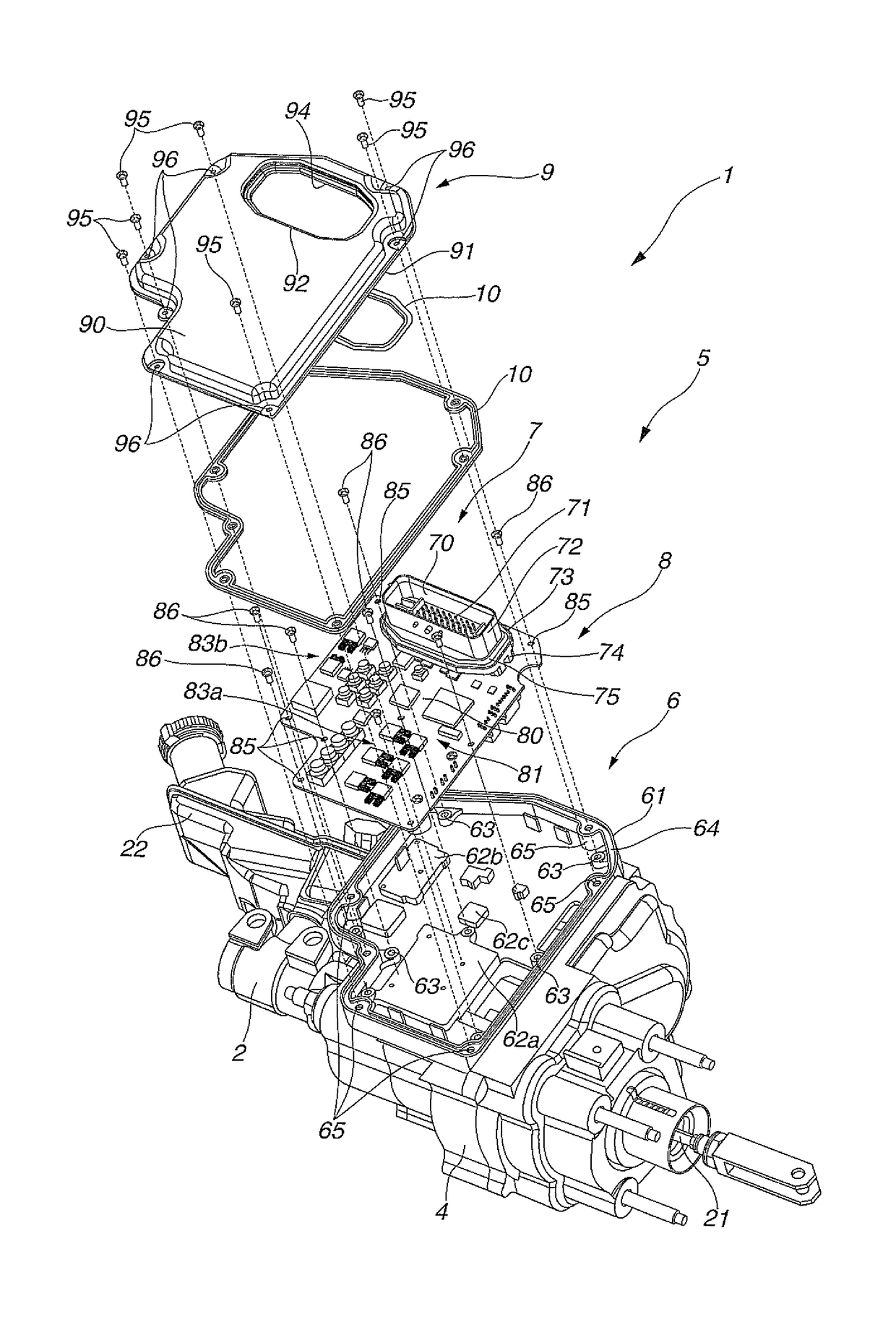
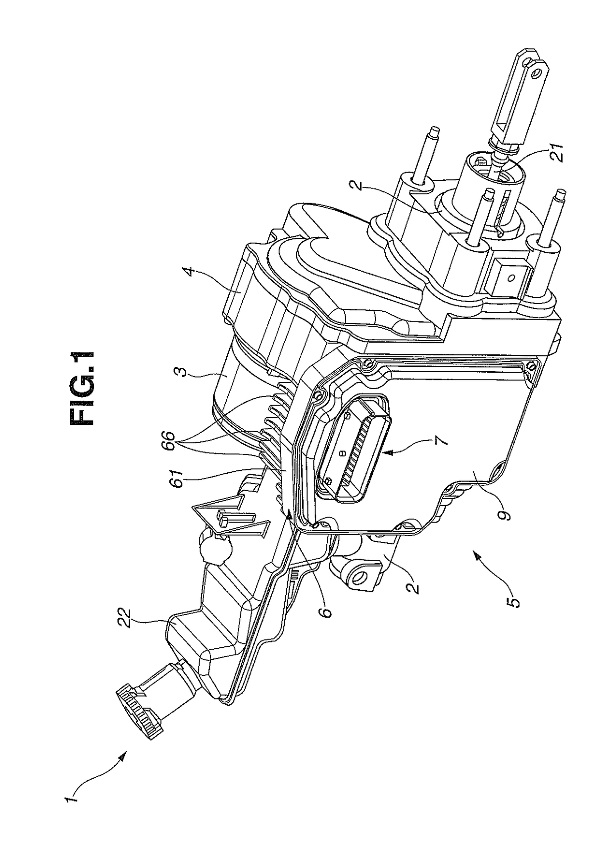
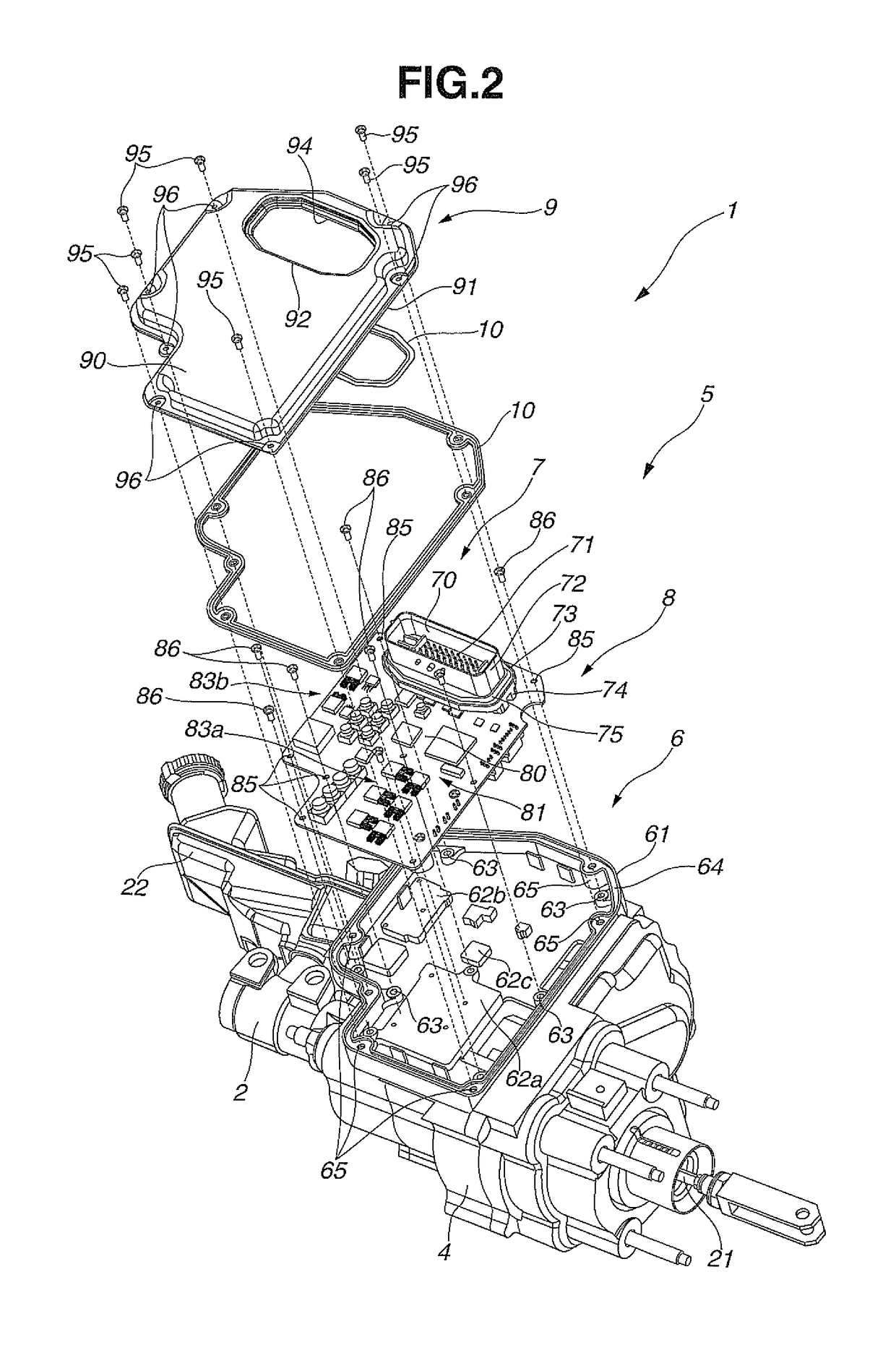
[0016]As shown in FIG. 1, a brake control apparatus for an automotive vehicle according to one embodiment of the present invention includes a master cylinder 2 that generates a hydraulic braking pressure by a piston thereof in response to operation of a brake pedal of the vehicle, an electric motor 3 that drives the master cylinder 2, a housing 4 in which the master cylinder 2 and the electric motor 3 are assembled and a control unit 5 combined with the housing 4 and adapted to perform drive control of the electric motor 3.

[0017]In the present embodiment, the master cylinder 2 and the electric motor 3 are arranged not to be coaxial with each other (that is, the master cylinder 2 and the electric motor 3 are in a biaxial arrangement) in the housing 4. The housing 4 has incorporated therein a known movement conversion mechanism for, when a rotor of the electric motor 3 is ...


PUM


Abstract

Disclosed is a brake control apparatus including a master cylinder that generates a hydraulic braking pressure in response to operation of a brake pedal, an electric motor that drives the master cylinder, a housing in which the master cylinder and the electric motor are assembled, and a control unit adapted to perform drive control of the electric motor. The control unit has a bottom formed at least partially integral with the housing and includes a circuit board mounting thereon drive elements to drive the electric motor. The brake control apparatus includes a heat radiating seat located on an inner surface of the bottom of the control unit at a position apart from the electric motor and closer to the master cylinder than the electric motor and brought into thermal contact with the circuit board so as to radiate heat of the drive elements toward the housing.

Description

BACKGROUND OF THE INVENTION[0001]The present invention relates to a brake control apparatus for controlling an actuator in an automotive brake system.[0002]Japanese Laid-Open Patent Publication No. 2011-219079 discloses, as an example of a brake control apparatus for controlling an actuator in an automotive brake system, a hydraulic brake assembly having a master cylinder driven by an electric motor under the control of a control unit. In this conventional brake control apparatus, the control unit is arranged adjacent to the electric motor. Due to such arrangement, there arise the problems of upsizing of the brake control apparatus and poor heat radiation performance and vibration resistance of the control unit.SUMMARY OF THE INVENTION[0003]The present invention has been made in view of the above problems. It is accordingly an object of the present invention to provide a brake control apparatus with an electric motor and a control unit so as to, while being downsized, improve the he...

Claims


Application Information

Patent Timeline
Patent Type & Authority Patents(United States)
IPC IPC(8): B60T13/74B60T11/10
CPCB60T13/745B60T11/103
Inventor NAKANO, KAZUHIKOWATANABE, HIROFUMIYASUKAWA, DAISUKE
Owner HITACHI ASTEMO LTD
Why Eureka
Try Eureka