Heat conduction member

a heat conductance and member technology, applied in the field of heat conductance members, can solve the problems of difficult to secure wettability, reduce durability, and breakage of the honeycomb structure, and achieve the effects of improving heat conductance, improving adhesion, and efficient discharg

Active Publication Date: 2017-08-22
NGK INSULATORS LTD
View PDF55 Cites 1 Cited by
  • Summary
  • Abstract
  • Description
  • Claims
  • Application Information

AI Technical Summary

Benefits of technology

[0009]In addition, in the case of integrating a cylindrical ceramic body with a metal pipe by press-fitting, the durability is reduced because of increase in thermal resistance by insufficient adhesion, breakage of heat conduction member by excessive precompression, and large residual stress remaining in the metal pipe.
[0020]Adhesion is improved by arranging an intermediate member made of a material having a Young's modulus of 150 GPa between the cylindrical ceramic body and the metal pipe on the outer periphery side of the cylindrical ceramic body. This improves heat conductance, and heat in the cylindrical ceramic body can efficiently be discharged outside the metal pipe. In addition, since the heat conductance is excellent in the axial (longitudinal) direction, heat on the tip (inlet) side can be released to the rear (outlet) side. In the case that a graphite sheet is used as the intermediate member, since side slipping is possible by the graphite sheet, stress due to the thermal expansion difference between the cylindrical ceramic body and the metal pipe is hardly caused. Though the joint portion of the metal pipe and cylindrical ceramic body is at risk of being exposed to a temperature up to about 150° C., graphite has a sufficient heat resistant temperature of 400° C. or more. In addition, it is in no danger of corrosion.

Problems solved by technology

However, in the case of integrating a ceramic honeycomb structure with a metal base material (metal pipe) as in the Patent Document 1, there arise a problem of thermal expansion caused in use to deteriorate adhesion between the honeycomb structure and the metal base material and a problem of thermal stress generation to cause breakage in the honeycomb structure.
In addition, in the case of integrating a cylindrical ceramic body with a metal pipe by press-fitting, the durability is reduced because of increase in thermal resistance by insufficient adhesion, breakage of heat conduction member by excessive precompression, and large residual stress remaining in the metal pipe.
In the case of integrating a cylindrical ceramic body with a metal pipe by brazing, it is difficult to secure wettability, and stress is caused by a thermal expansion difference.

Method used


Image

  • Heat conduction member
  • Heat conduction member
  • Heat conduction member

Examples


example 1

Preparation of Kneaded Material

[0093]In the first place, 70 mass % of SiC powder having an average particle diameter of 45 μm, 10 mass % of SiC powder having an average particle diameter of 35 μm, and 20 mass % of SiC powder having an average particle diameter of 5 μm were mixed together to prepare a mixture of SiC powders. To 100 parts by mass of the mixture of SiC powders were mixed 4 parts by mass of a binder and water, and they were kneaded with a kneader to obtain a kneaded material. The kneaded material was put in a vacuum kneader to manufacture a circular columnar kneaded material.

[0094](Extrusion)

[0095]Next, the kneaded material was extruded to form a honeycomb formed body. In the extrusion, by selecting a die and a jig each having an appropriate form, the shape and thickness of the outer peripheral wall, the thickness of the partition wall, the cell shape, and the cell density were made desirable. A die made of superhard alloy which hardly abrades away was used. Regarding t...

examples 1 to 9

, Reference Example, Comparative Examples 1 and 2

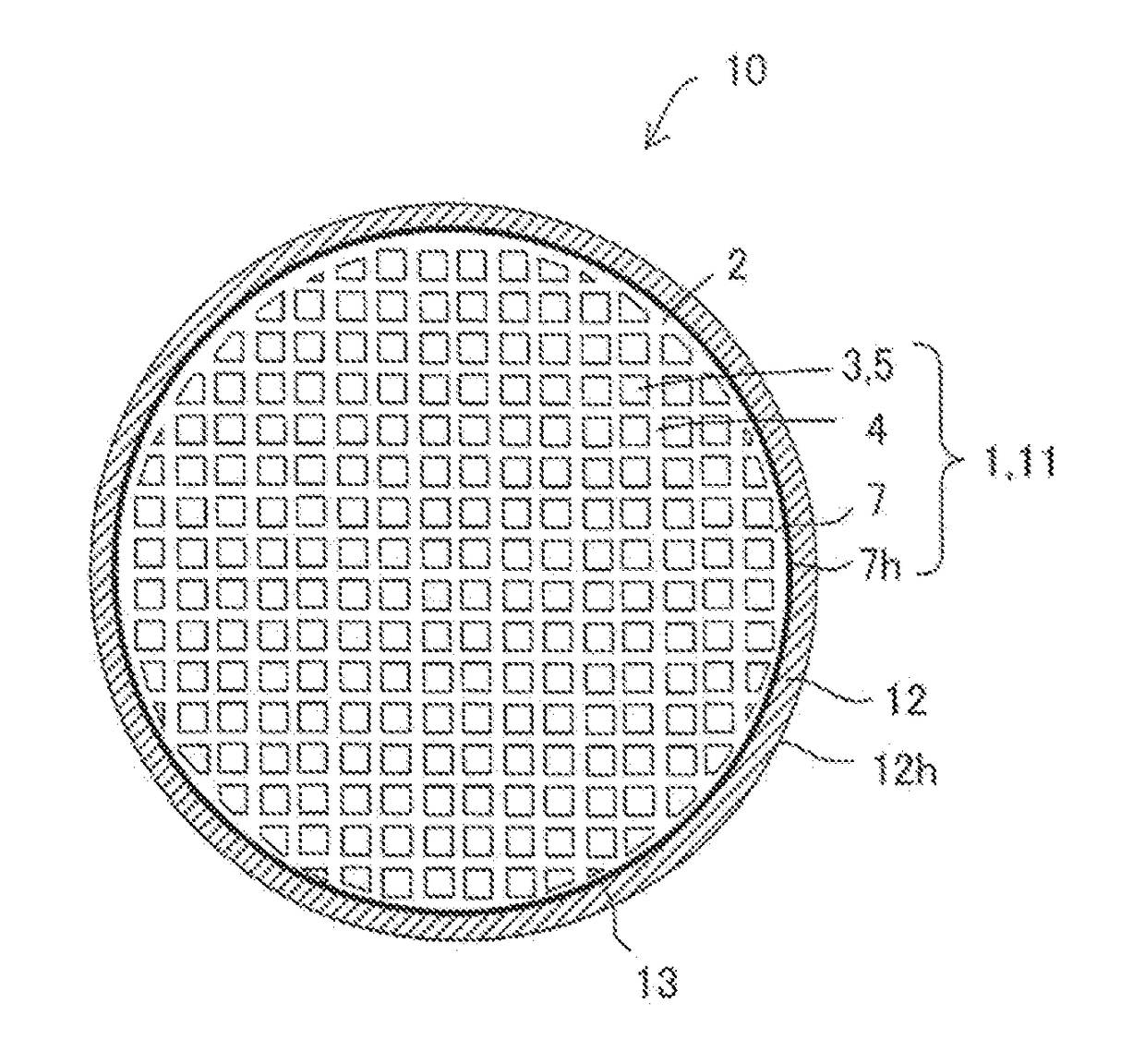
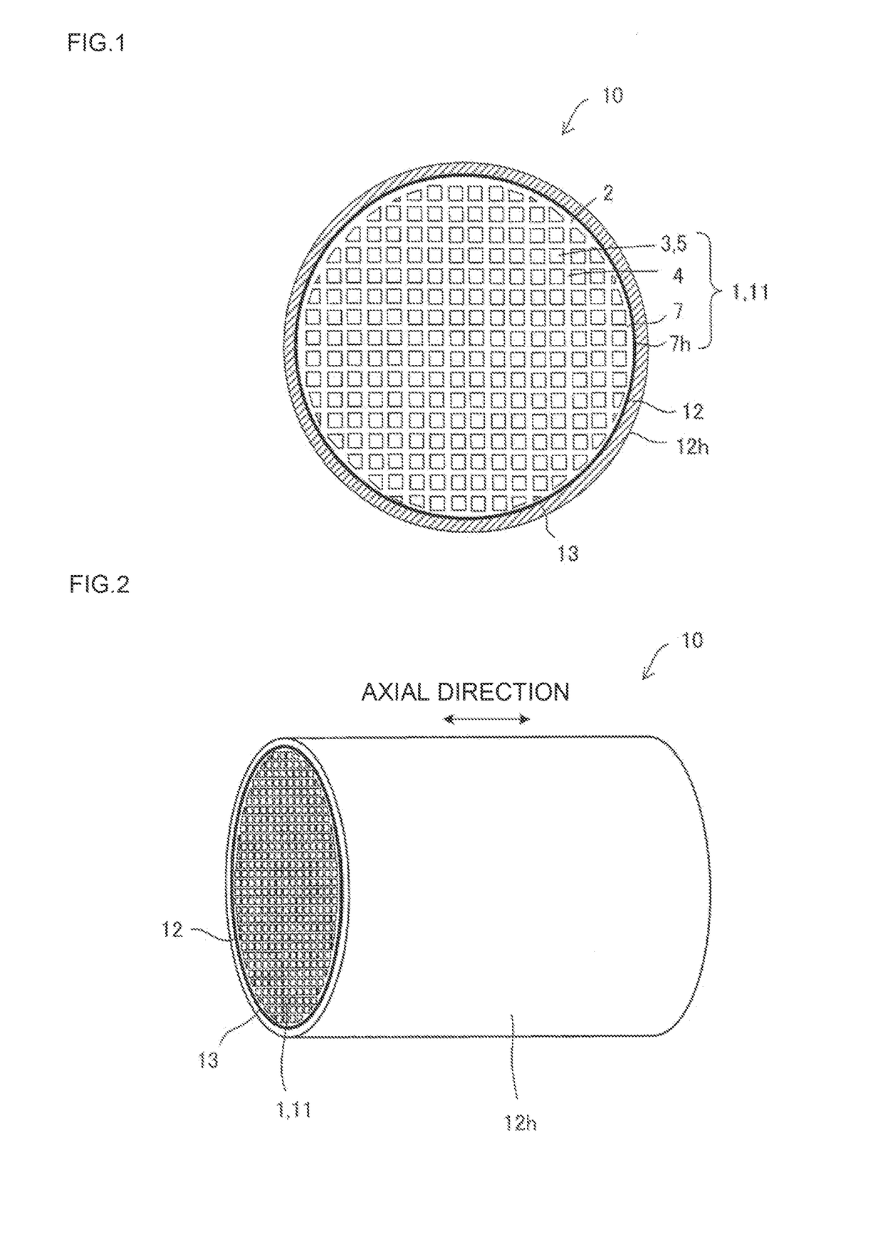
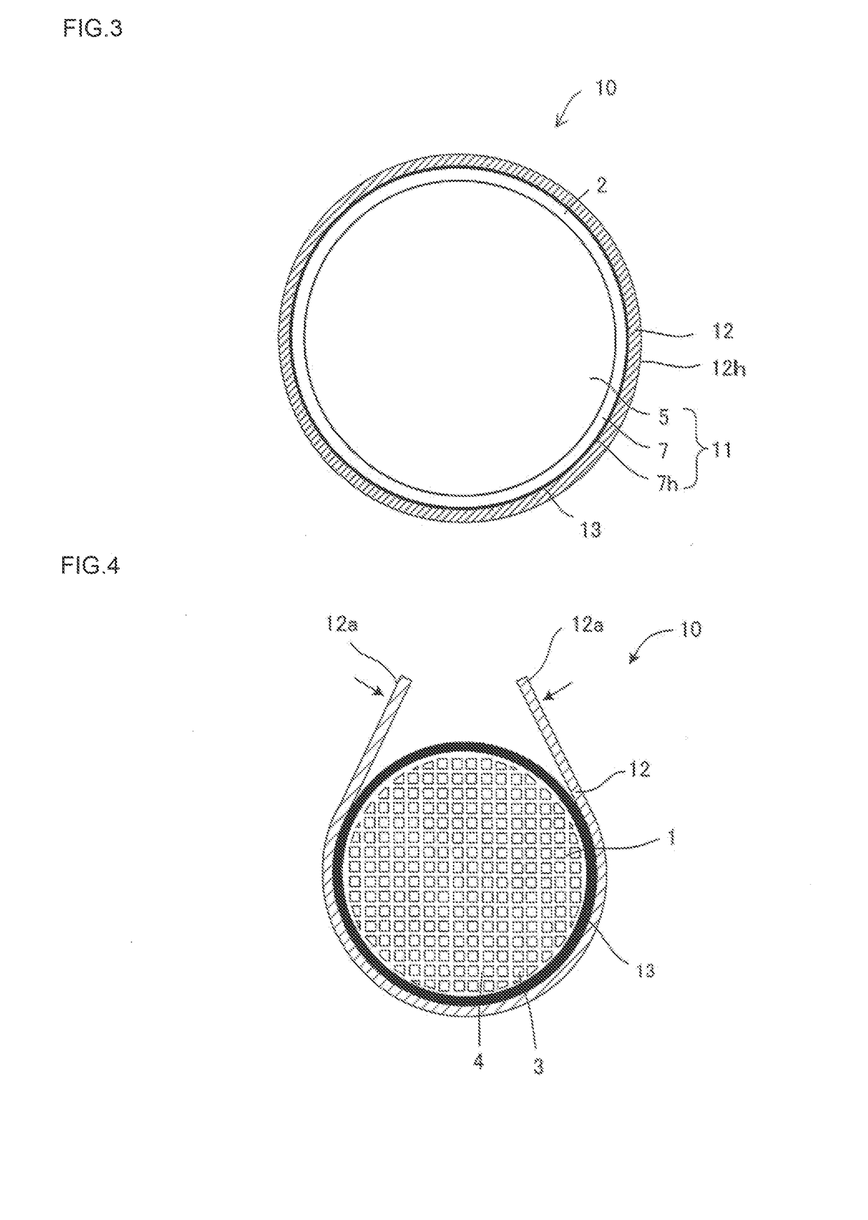
[0112]Furthermore, each of the other intermediate members 13 was subjected to the same heat transfer test to obtain the heat transfer efficiency. In addition, after the heat transfer efficiency test, presence / absence of crack generation in the cylindrical ceramic body 11 was checked. It is shown in Table 2. Example 1, Reference Example, and Comparative Example 1 of Table 2 were the same as in Table 1. The structure was “cylindrical ceramic body 11+intermediate member 13+metal pipe 12” except for Reference Example and Comparative Example 1. The structure of Reference Example was a single body of a cylindrical ceramic body 11, and the structure of Comparative Example 1 was cylindrical ceramic body 11+metal pipe 12 with no intermediate member 13.

[0113]

TABLE 2Evaluation resultIntermediate memberHeatPresence / Young'stransferAbsencemodulusThicknessefficiencyof crackMaterialGPamm%generationExample 1Graphite0.10.258.2AbsentsheetExample 2Graphi...


PUM

PropertyMeasurementUnit
Young's modulusaaaaaaaaaa
thicknessaaaaaaaaaa

Abstract

A heat conduction member includes: a cylindrical ceramic body, a metal pipe on the outer periphery side of the cylindrical ceramic body, and an intermediate member held between the cylindrical ceramic body and the metal pipe. The cylindrical ceramic body has passages passing through from one end face to the other end face and allowing the first fluid to flow therethrough. The intermediate member is made of material having at least a part having a Young's modulus of 150 Gpa or less. The first fluid is allowed to flow through the inside of the cylindrical ceramic body while the second fluid having lower temperature than that of the first fluid is allowed to flow on the outer peripheral face side of the metal pipe to perform heat exchange between the first fluid and the second fluid.

Description

BACKGROUND OF THE INVENTION[0001]1. Field of the Invention[0002]The present invention relates to a heat conduction member where a cylindrical ceramic body is covered with a metal pipe.[0003]2. Description of Related Art[0004]Heat can be used effectively by heat exchange from a high temperature fluid to a low temperature fluid. For example, there is a heat recovery technique of recovering heat from high temperature gas such as combustion exhaust gas of an engine or the like. As a gas / liquid heat exchanger, a fin-provided tube-shaped heat exchanger of an automobile radiator, an air-conditioning outdoor unit, or the like is general. However, for recovering heat from gas such as automobile exhaust gas, it is difficult to use a general metal heat exchanger at high temperature because it has poor heat resistance. Therefore, heat resistant metals and ceramic materials having heat resistance, thermal shock resistance, corrosion resistance, and the like are suitable. However, heat resistant ...

Claims


Application Information

Patent Timeline
Patent Type & Authority Patents(United States)
IPC IPC(8): F28D7/10B01J35/04F28D21/00F28F21/08F28F21/04F28F1/00F01N13/16F01N3/05B01D46/24F01N3/02F28F13/00C04B37/02C04B37/00C04B35/565F01N3/04F01N3/28
CPCF28D7/106B01D46/2429B01J35/04C04B35/565C04B37/008C04B37/021F01N3/055F01N13/16F28D21/0003F28F1/003F28F13/003F28F21/04F28F21/08B01D46/2448C04B2235/3826C04B2235/428C04B2235/5436C04B2235/5472C04B2235/606C04B2235/9607C04B2237/363C04B2237/365C04B2237/84F01N3/043F01N3/046F01N3/2889F01N2260/02F28F2013/006F28F2265/26F28F2275/127Y02T10/20Y02T10/12B01D46/24494B01D46/24495
Inventor YOSHIDA, SHINYATAKAHASHI, HIRONORIKAWAGUCHI, TATSUO
Owner NGK INSULATORS LTD
Why Eureka
Try Eureka