Liquid crystal display device

a technology of liquid crystal display and display device, which is applied in the direction of optics, instruments, optical light guides, etc., can solve the problems of increased electric power consumption and increased heat emission of leds, and achieve the effect of preventing non-uniform luminan

Active Publication Date: 2015-05-05
JAPAN DISPLAY INC
View PDF2 Cites 1 Cited by
  • Summary
  • Abstract
  • Description
  • Claims
  • Application Information

AI Technical Summary

Benefits of technology

[0011]Additionally, vehicular liquid crystal display devices need to provide high luminance compared with other liquid crystal display devices. Implementation of this, on the other hand, involves more consumption of electric power in the LEDs that form the light source, and hence a greater deal of heat emission from the LEDs. The backlight is preferably placed in a metal to release the LED-emitted heat more efficiently.
[0015]Referring to FIG. 9, a reflecting sheet 12 is placed on the lower frame 40, and the light guide plate 10 is placed on the reflecting sheet 12. The reflecting sheet 12 and the light guide plate 10 work to direct LED-emitted incident light from the side faces of the light guide plate 10 so the liquid crystal display panel. Optical sheets, including a diffusion sheet and a prism sheet, are mounted on the light guide plate 10. The optical sheets 18 function to raise utilization efficiency of the light, to reduce nonuniformity in luminance of the backlight, and to minimize moiré. The flexible wiring substrate 80, connected to the terminal section of the liquid crystal display panel, extends to the rear of the lower frame 40 and is connected to a printed wiring substrate 90 via a connector 81. The printed wiring substrate 90 is protected with a substrate cover 50 formed of a metal. A combination of such liquid crystal display panel and backlight as shown in FIG. 9 is hereinafter called the liquid crystal display device.
[0020]An object of the present invention is to prevent the movement of the light guide plate 10 due to vibration and at the same time to avoid distortion of the optical sheets 16 by preventing the light guide light 10 from moving the optical sheets 18 into contact with the middle frame 30, and thereby prevent the nonuniformity of luminance on the screen from occurring.
[0026]In accordance with the present invention, the protrusions at the four corners of the light guide plate prevent the light guide plate from moving the optical sheets into contact with the middle frame and distorting the optical sheets, and thereby prevent nonuniformity of luminance on a display screen from occurring.
[0027]In addition, in accordance with the present invention, the gap between the middle frame and the light guide plate or the protrusions of the light guide plate does not need to be increased, which prevents the light guide plate iron; moving or generating vibration sounds, even in case of vibration.

Problems solved by technology

Implementation of this, on the other hand, involves more consumption of electric power in the LEDs that form the light source, and hence a greater deal of heat emission from the LEDs.

Method used


Image

  • Liquid crystal display device
  • Liquid crystal display device
  • Liquid crystal display device

Examples


first embodiment

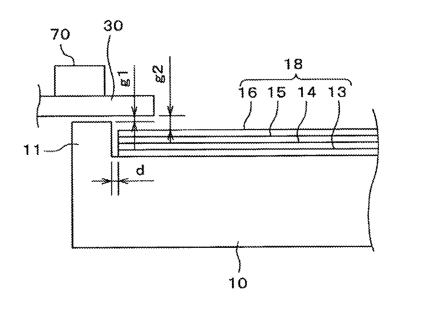
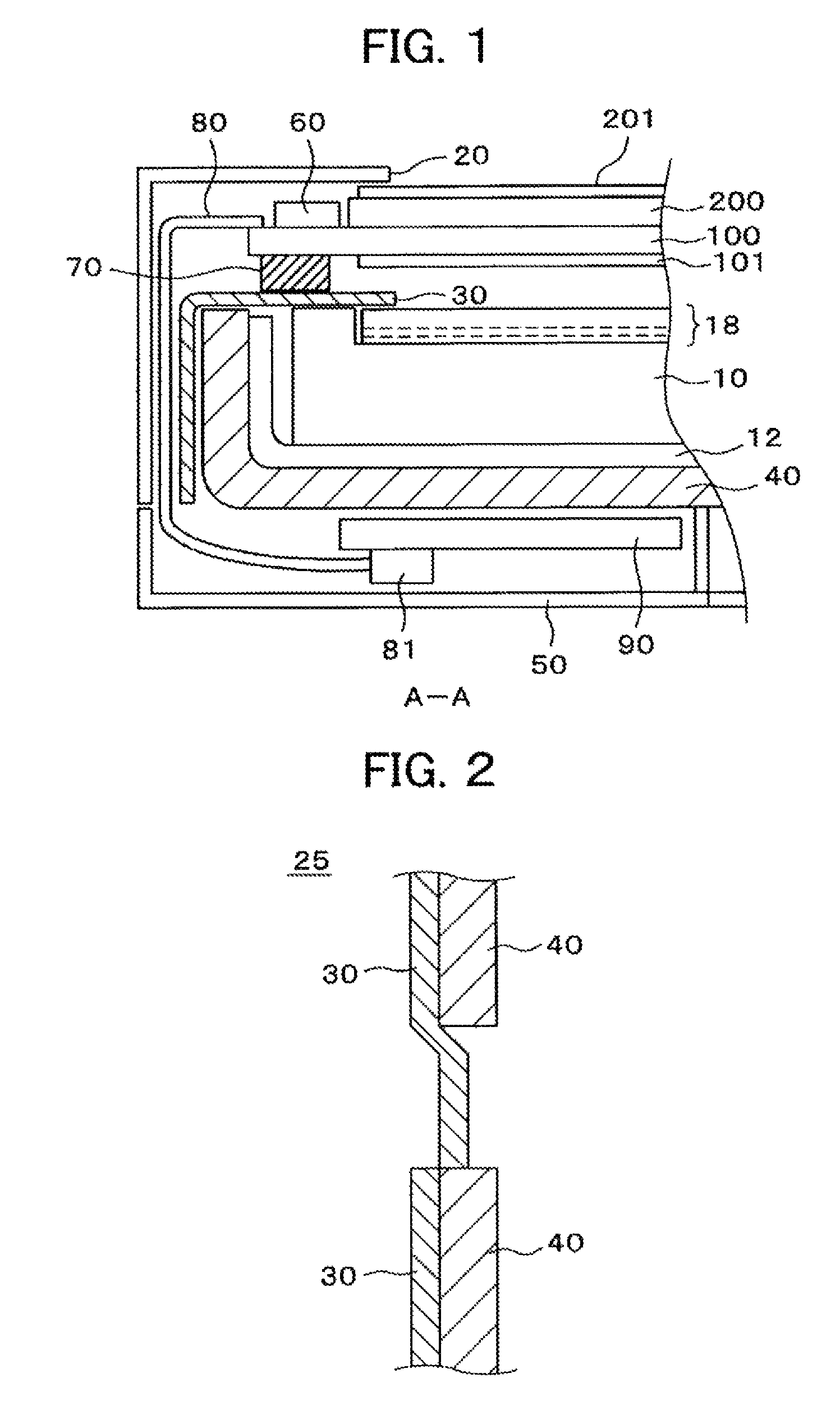
[0040]FIG. 1 is a sectional view of a liquid crystal display device embodying the present invention. FIG. 1 shows section A-A of the liquid crystal display device shown in FIG. 8. Description of FIG. 8 is omitted here since the figure has already been described earlier in this specification. Referring to FIG. 1, a backlight, disposed in a middle frame 30 and a lower frame 40, is present in the back of the liquid crystal display device, and the backlight is covered in its entirety with an upper frame 20. In these respects, the liquid crystal display device is the same as that described in FIG. 9. An IC driver 60 is disposed at a terminal section of a TFT substrate 100, a flexible wiring substrate 80 is connected to the terminal section, and the flexible wiring substrate 80 extends near the back of the lower frame 40 and is connected to a printed wiring substrate 90 in the back of the lower frame 40 via a connector 81. In these respects, the liquid crystal display device is also the s...


PUM

PropertyMeasurementUnit
temperatureaaaaaaaaaa

Abstract

Occurrence of an event can be prevented, whereby, when a backlight expands with heat, a light guide plate might move a group of optical sheets into contact with a middle frame and deform the sheets, thereby causing nonuniformity of luminance on a screen. In particular, a protrusion is formed at an edge of the plate, and the sheets are mounted on the plate to avoid the protrusion. The frame covers the protrusion and the edge of the sheets. Even if a spatial gap with respect to the frame is lost by expansion of the plate, the sheets suffer no deformation due to interference between an edge of the sheets and the frame. Therefore, the nonuniformity of luminance on the screen does not occur, either. Also, unusual sounds due to movement of the plate under vibration do not arise since a gap between the protrusion and the frame can be small.

Description

CLAIM OF PRIORITY[0001]The present application claims priority from Japanese Patent Application JP 2012-278309 filed on Dec. 20, 2013, the content of which is hereby incorporated by reference into this application.BACKGROUND OF THE INVENTION[0002]1. Field of the Invention[0003]The present invention relates generally to liquid crystal display devices, and more particularly to a vehicular, compact liquid crystal display device slimmed down in bezel region size for increased display region.[0004]2. Description of the Related Art[0005]A conventional liquid crystal display device include: a thin-film transistor (TFT) substrate formed with pixel electrodes, TFTs, and other elements in matrix form; a counter substrate disposed in facing relation with respect to the TFT substrate and formed with a color filter and other elements at locations corresponding to the pixel electrodes on the TFT substrate; and liquid crystals arranged between the TFT substrate and the counter substrate. The displ...

Claims


Application Information

Patent Timeline
Patent Type & Authority Patents(United States)
IPC IPC(8): G02F1/1333F21V8/00G02F1/1335
CPCG02B6/0088G02F1/133615G02F1/133305G02F1/133605G02B6/0085G02F2201/54G02F2203/60
Inventor MIYAZAKI, HIROYUKI
Owner JAPAN DISPLAY INC
Why Eureka
Try Eureka