

Reduced false alarm security system
- Summary
- Abstract
- Description
- Claims
- Application Information
AI Technical Summary
Benefits of technology
Problems solved by technology
Method used
Image

Examples
Embodiment Construction
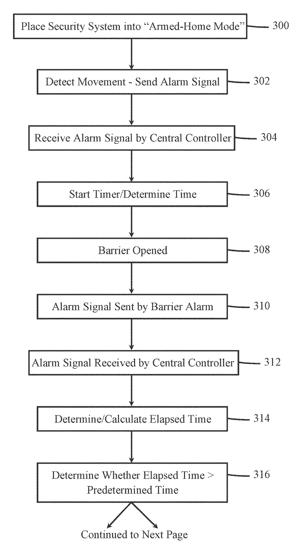
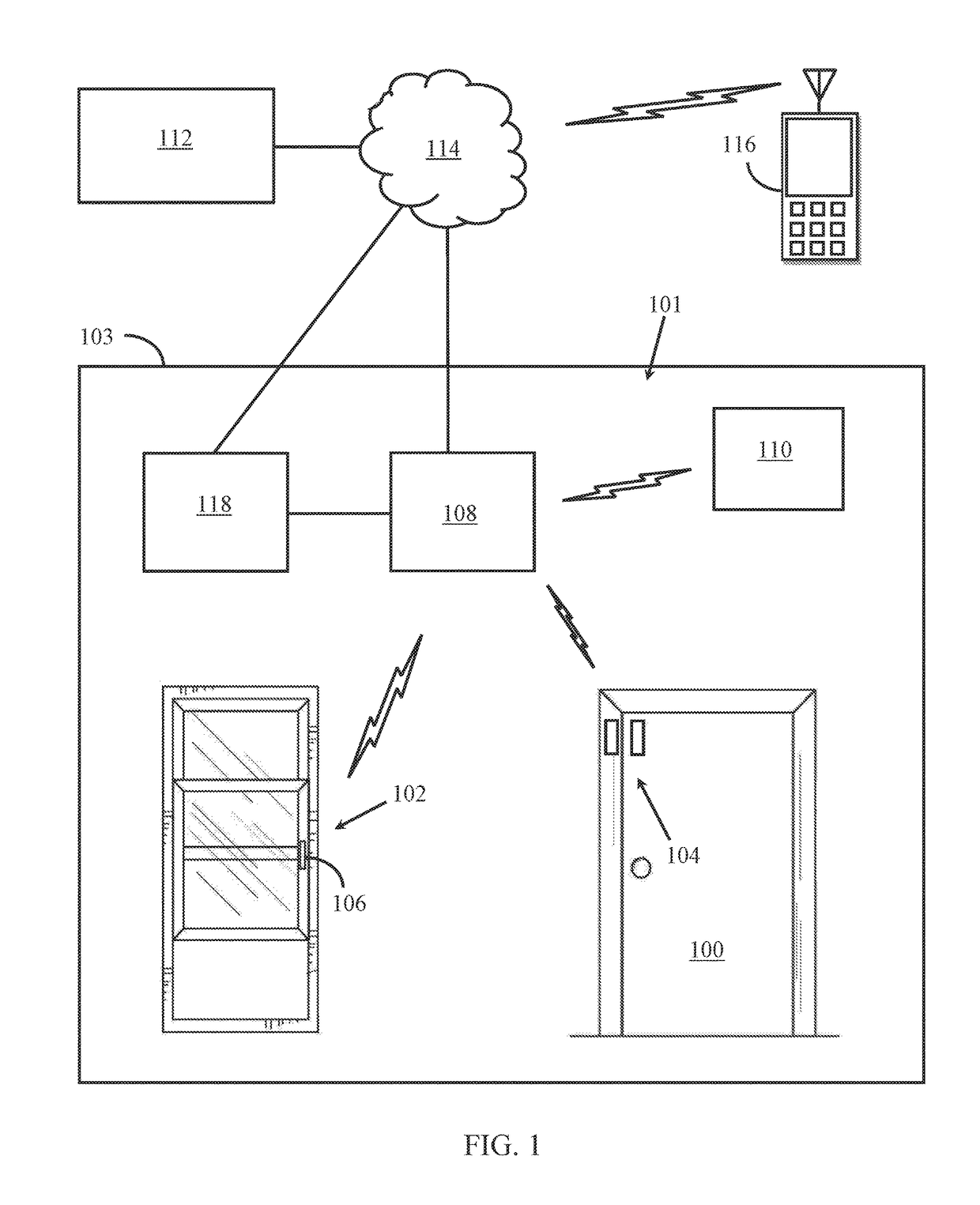
[0013]The present application relates to a security system for reducing the occurrence of false alarms. In one embodiment, such a system uses standard door and window sensors and an occupancy sensor (such as a standard motion detector), each in communication with a central security monitoring device. The central security monitoring device receives signals from the door and window sensors and from the occupancy sensor when doors and windows are opened and when a person is detected inside a building, by the door and window sensors and the occupancy sensor, respectfully. The central security monitoring device uses the signals from these sensors to determine whether a false alarm has occurred when a door or window is opened. For the purpose of the discussions herein, the term entry barrier means a door, a window, a gate, a garage door, or some other object that prevents entry to a building, such as a home or business.
[0014]FIG. 1 is an illustration of a security system 101 inside a buil...
PUM
 Abstract
Description
Claims
Application Information