Clock synchronization for line differential protection

a clock synchronization and line differential technology, applied in multiplex communication, fault response, instruments, etc., can solve the problems of costly, unreliable, and inability to always be reliable in synchronizing with a master clock, so as to reduce the determined clock offset

Active Publication Date: 2017-04-04
HITACHI ENERGY LTD
View PDF24 Cites 1 Cited by
  • Summary
  • Abstract
  • Description
  • Claims
  • Application Information

AI Technical Summary

Benefits of technology

[0026]The present disclosure also relates to an arrangement for synchronizing a first clock and a second clock located respectively at a first end and a second end of a power line. In accordance with an exemplary embodiment, the arrangement includes a recorder for measuring a first representation of an oscillating power line quantity such as current at a first end of the power line and for time-stamping the first representation by the first clock. The arrangement also includes a receiver for receiving a second representation of the oscillating power line quantity measured at the second end of the power line and time-stamped by the second clock. The apparatus includes a comparator for comparing the first representation and the second representation to determine a clock offset between the first clock and the second clock. In addition, the arrangement includes a clock adjuster for adjusting the first clock to reduce the determined clock offset.
[0027]Given an initial fault-free state of the power transmission line, the present disclosure synchronizes clocks located at ends of a power transmission line based on a measured and time-stamped representation with high precision and reliability. This way, the present disclosure can be used as a stand-alone or add-on synchronization method overcoming shortcomings of other, for example, network or GPS based, synchronization methods.

Problems solved by technology

Economic and environmental requirements lead to operation of power transmission lines close to their operating limits.
Any fault will cascade into a system wide disturbance causing widespread outages for a tightly interconnected system operating close to its limits.
However, synchronization with a master clock can neither be always reliable nor cost effective.
Reception of a GPS based synchronization signal can be costly and even unreliable, as communication with the satellite can be interrupted for example, by radio interference or severe weather conditions impairing signal propagation.
In addition, network-based synchronization assumes communication delays between clocks to be symmetric, i.e. equal in both directions, an assumption which is not generally guaranteed.

Method used


Image

  • Clock synchronization for line differential protection
  • Clock synchronization for line differential protection
  • Clock synchronization for line differential protection

Examples


Embodiment Construction

[0013]Exemplary embodiments of the present disclosure increase the reliability of protection systems for a power transmission line, for example, to improve clock synchronization of such a system.

[0014]Exemplary embodiments of the present disclosure provide a method and an arrangement for synchronizing clocks located at opposite ends of a power line.

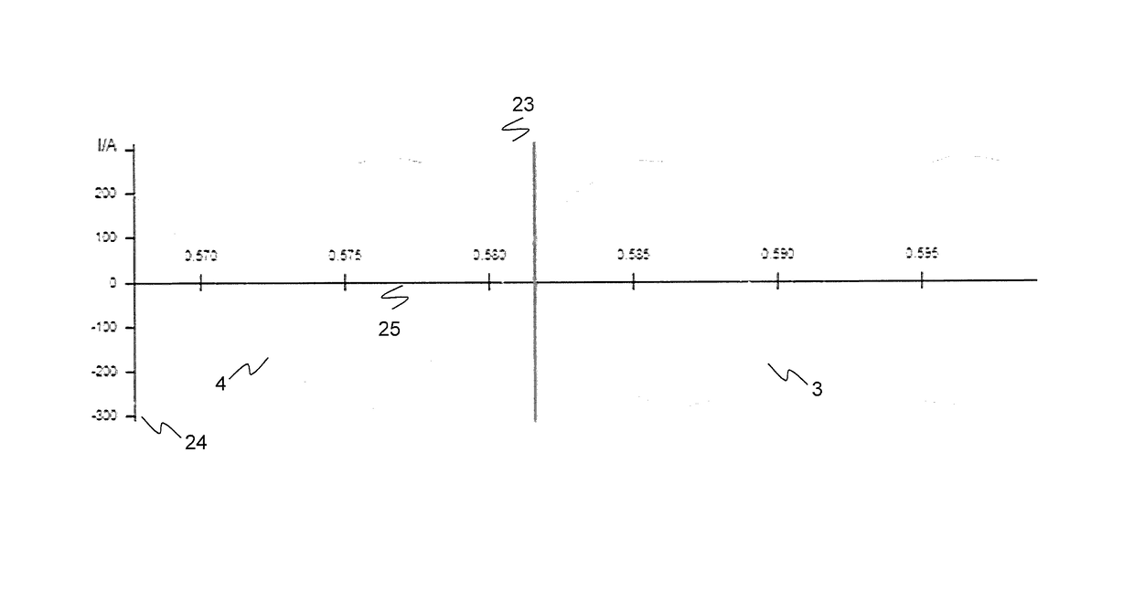
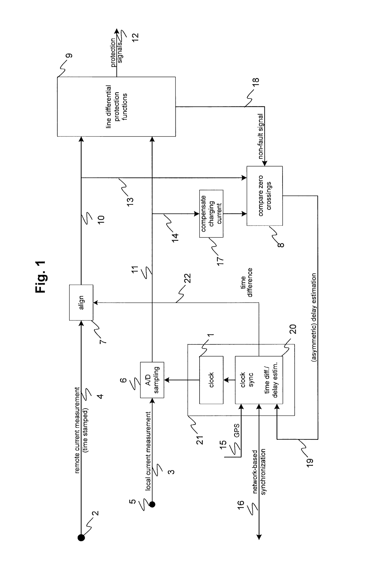
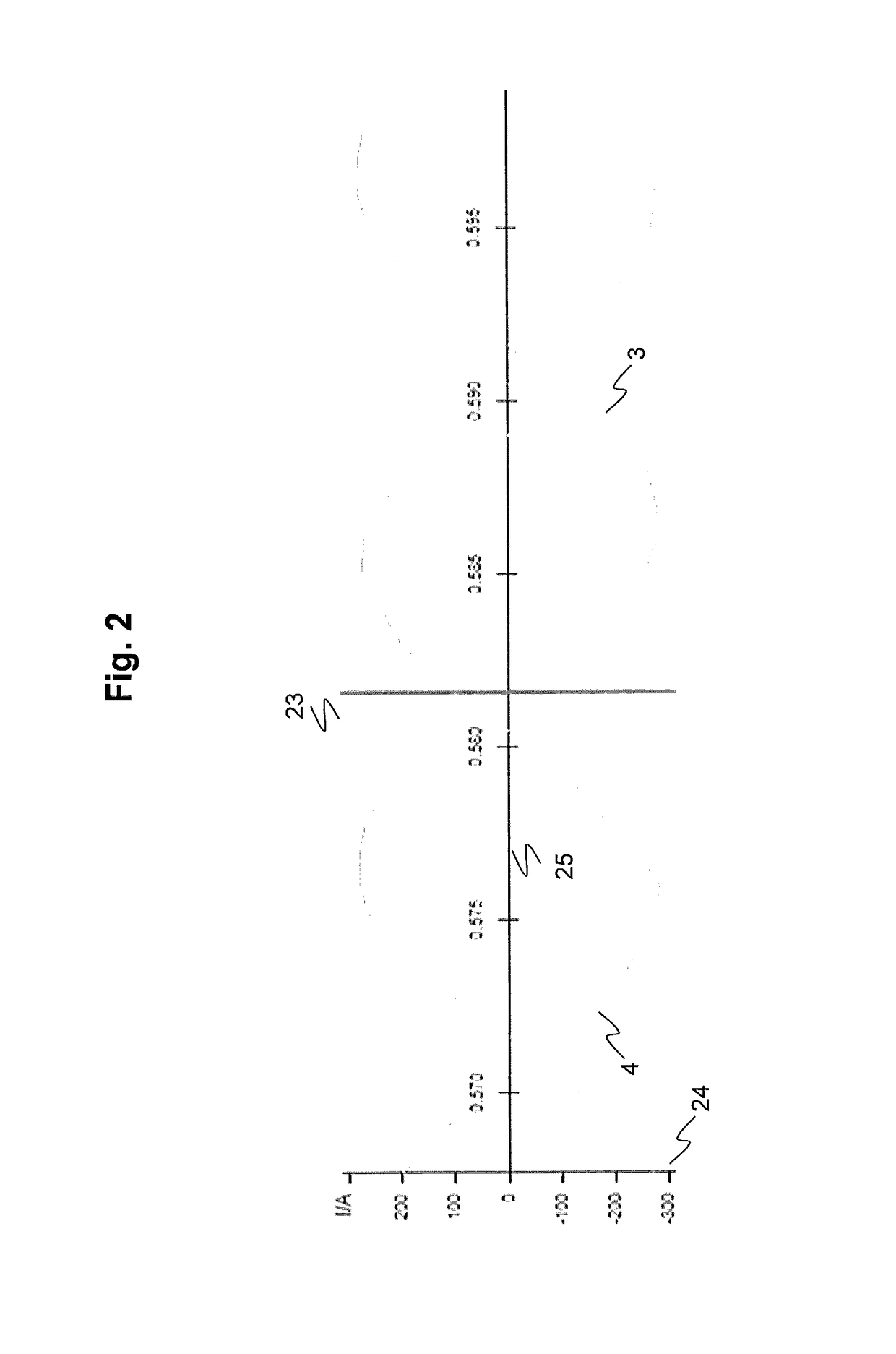
[0015]According to an exemplary embodiment of the present disclosure, a first clock and a second clock located respectively at a first end and a second end of an AC power line are aligned according to an oscillating power line quantity such as a current, for example. The two clocks are initially synchronized to be within a period of a frequency of the power line quantity. In order to synchronize the clocks, a first representation such as a waveform of an oscillating power line quantity is produced by measuring the power line quantity at the first end of the power line. For example, the quantity can be measured or recorded with a sufficien...


PUM


Abstract

A method and arrangement are provided for time synchronization between two geographically separated stationary clocks, such as first and second clocks located respectively at first and second ends of an AC power line. A first representation of an oscillating power line quantity is produced by measuring or recording the power line quantity at the first end of the power line, and time-stamping the first representation by the first clock. A second representation of the same oscillating power line quantity is produced by measuring the power line quantity at the second end of the power line, and time-stamping the second representation by the second clock. The first and second representations are compared to determine a clock offset between the first and second clocks. Based on the comparison, one or both of the first and second clocks are adjusted to reduce the determined clock offset.

Description

RELATED APPLICATION[0001]This application claims priority under 35 U.S.C. §119 to European Patent Application No. 12178590.1 filed in Europe on Jul. 31, 2012, the entire content of which is hereby incorporated by reference in its entirety.FIELD[0002]The present disclosure relates to the field of time synchronization between two geographically separated stationary clocks, for example, clocks at two ends of a power transmission line.BACKGROUND INFORMATION[0003]Power transmission lines are a crucial part of any electrical distribution system, as they provide a path to transfer power between generation and consumer. Power transmission lines are closely interconnected for a reliable operation. Economic and environmental requirements lead to operation of power transmission lines close to their operating limits. Any fault will cascade into a system wide disturbance causing widespread outages for a tightly interconnected system operating close to its limits. Therefore, transmission protecti...

Claims


Application Information

Patent Timeline
Patent Type & Authority Patents(United States)
IPC IPC(8): H02H3/28G06F11/16H04B1/7073H02J3/08H04J3/06
CPCH04B1/7073H02H3/28G06F11/1658H02J3/08H04J3/0667Y02E60/00
Inventor DZUNG, DACFEY
Owner HITACHI ENERGY LTD
Why Eureka
Try Eureka