Optical interference tomographic apparatus, and method for controlling optical interference tomographic apparatus

Active Publication Date: 2017-04-11
CANON KK
View PDF5 Cites 11 Cited by
  • Summary
  • Abstract
  • Description
  • Claims
  • Application Information

AI Technical Summary

Benefits of technology

[0009]The present invention is designed with respect to the above described problems, and an object of the present invention is to provide an optical interference tomographic apparatus which can obtain a tomographic image having a desired contrast and the like, regardless of a scanned position, and to provide a method for controlling the optical interference tomographic apparatus.

Problems solved by technology

After this, reflected light or back scattered light of the measuring light, which is obtained from the eye to be inspected, interferes with the reference light, and interference light is obtained.

Method used


Image

  • Optical interference tomographic apparatus, and method for controlling optical interference tomographic apparatus
  • Optical interference tomographic apparatus, and method for controlling optical interference tomographic apparatus
  • Optical interference tomographic apparatus, and method for controlling optical interference tomographic apparatus

Examples


Embodiment Construction

[0021]Preferred embodiments of the present invention will now be described in detail in accordance with the accompanying drawings.

[0022]Incidentally, the following embodiments do not limit the present invention involving the scope of the claims, and all of combinations of features described in the present embodiments are not necessarily indispensable for the means for solving the problem in the invention. In addition, the same reference number designates the same component throughout the following description.

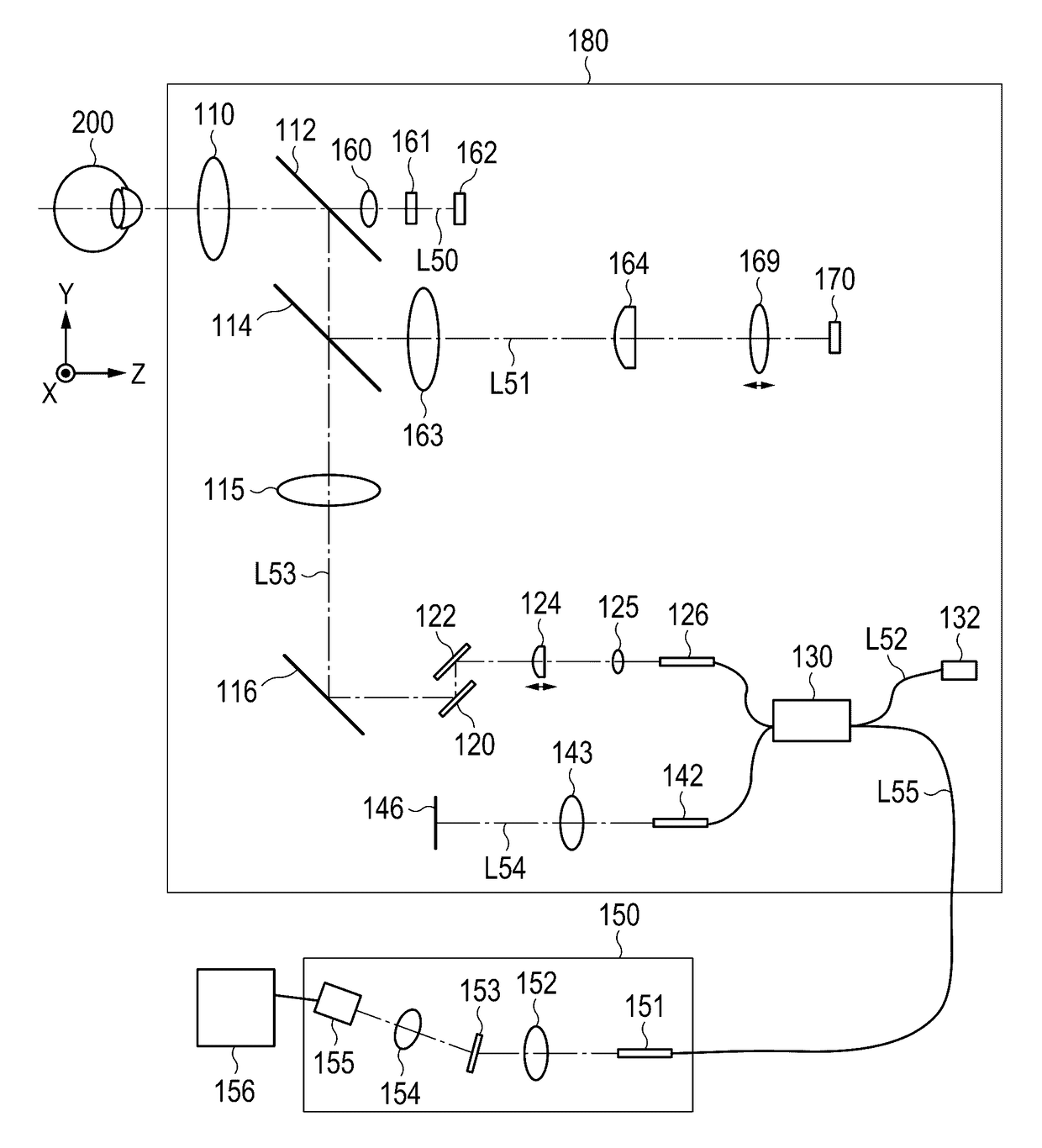
[0023]FIG. 1 illustrates a block diagram of an OCT apparatus in the present embodiment. The OCT apparatus has an optical head 180 and a spectroscope 150. The optical head 180 has a mechanism for scanning the eye 200 to be inspected with measuring light, and a mechanism for making return light reflected from the eye 200 to be inspected interfere with reference light. The spectroscope 150 has a mechanism for processing interference light provided by the optical head 180, as a tom...


PUM


Abstract

In order to acquire a tomographic image of the eye to be inspected with high precision even in case where an optical path length and intensity vary depending on a scanned position in an OCT apparatus acquiring the tomographic image of a predetermined part of an object to be inspected, based on the intensity of interference light obtained by combining return light from the object that has been irradiated with the measuring light, with reference light corresponding to the measuring light, includes: a scanning optical system which scans the object with the measuring light in an optical path of the measuring light; an image forming unit which generates the tomographic image based on the intensity of the interference light; and an image correcting unit which subjects the tomographic image to a correction process appropriate to the scanned position with the measuring light on the object.

Description

BACKGROUND OF THE INVENTION[0001]Field of the Invention[0002]The present invention relates to an optical interference tomographic apparatus, and a method for controlling the same.[0003]Description of the Related Art[0004]Currently, an optical interference tomographic apparatus (hereinafter referred to as OCT apparatus) for performing OCT (Optical Coherence Tomography) which uses interference of light waves is widely used in diagnosis in an ophthalmology field. This OCT apparatus divides light of a low-coherence light source into measuring light which irradiates an eye to be inspected, and reference light, and irradiates the eye to be inspected with the measuring light. After this, reflected light or back scattered light of the measuring light, which is obtained from the eye to be inspected, interferes with the reference light, and interference light is obtained. A tomographic signal at some position of the eye to be inspected can be acquired from the interference light. When the eye...

Claims


Application Information

Patent Timeline
Patent Type & Authority Patents(United States)
IPC IPC(8): A61B3/14A61B3/10G01B9/02
CPCA61B3/102G01B9/02044G01B9/02075G01B9/02083G01B9/02091
Inventor YAMASHITA, RISA
Owner CANON KK
Why Eureka
Try Eureka