Direct control of X-ray focal spot movement

a technology of x-ray and focal spot, applied in the field of direct control of x-ray focal spot movement and x-ray imaging system, can solve problems such as the complexity that the medical staff has to manage, and achieve the effect of reducing the complexity of a workflow

Inactive Publication Date: 2017-04-11
KONINKLIJKE PHILIPS ELECTRONICS NV
View PDF11 Cites 2 Cited by
  • Summary
  • Abstract
  • Description
  • Claims
  • Application Information

AI Technical Summary

Benefits of technology

[0004]Hence, it can be an object of the present invention to reduce complexity of a workflow in a hospital environment when X-ray imaging is used.
[0009]The image acquisition unit is adapted to generate the image comprising an X-ray source, an X-ray detector, and additional mounting or processing means. The image acquisition unit can adapt different projection directions related to a volume of interest, for instance a patient. The volume of interest describes the area or spatial portion of an object, for instance a human body. The two acquired images are supposed to provide different views which can help to capture the spatial dimensions of the examined object. This can be important in particular for certain interventions where it is necessary to navigate a surgical instrument such as a catheter within the human body. The doctor obtains a more realistic impression of the spatial conditions of a particular region within the body.
[0010]According to an example it may be necessary to generate images from different spatial directions to calculate a three-dimensional projection. The first image is acquired before the change of the projection direction, the second image is acquired after the change of the projection direction. The change of projection directions may be necessary multiple times during a surgery. Because the change of the imaging direction only requires very simple and intuitive instructions disturbances and distractions are reduced. The ease of use can be significantly increased.
[0012]Also, 3D glasses which allow a three-dimensional presentation of the image are possible. The described glasses can also comprise small LCD displays positioned directly in front of the user's eyes. This allows to display two different images, each image specifically generated for one particular eye of the user.
[0015]Lenticular (autoscopic) displays with n views and holographic displays allow direct 3D viewing without need for special glasses.
[0020]The change in a viewing-direction means that the user changes his position in relation to the image displayed on the display. Adapting means can be any type of mechanical, magnetic, electrical or any other type of means that are able to change the projection direction of the imaging system. Mechanical means can be for instance a movable C-arch, a movable patient table, a movable X-ray source, a movable X-ray detector, or any other type of movable mechanical components. Electrical or electromagnetic adapting means can comprise for instance deflection control means for moving an X-ray focal spot on an X-ray tube anode, or switching between two or more cathodes of an X-ray source. The advantage of electrical or electromagnetic adapting means is that no mechanical movements are necessary which would further disturb the workflow or distract medical staff. In opposite to mechanical movements, electrical adaptation or electromagnetic adaptation performed in much less time. In particular, a focal spot movement has many advantages over a mechanical adaptation in terms of the required time to adjust the projection direction of the imaging system. There can also be combinations of electromagnetic or electrical adjustments and mechanical adaption, for instance a movement of the C-arch is performed simultaneously with a focal spot movement or in a timely sequence. The correlation between the projection direction and the server viewing-direction describes a defined dependency between the two directions. In other words, the change of the projection direction depends on the strength or intensity of the user's input gesture. The advantage of the correlation between the projection direction and the change in viewing-direction is that the user can control the degree of change by the strength or intensity of the user's input gesture. The user input can also be based on voice commands, for instance to start a projection direction change process and a second voice command to stop this process.

Problems solved by technology

In particular, the simultaneous activities of actively controlling an imaging system and performing medical interventions at a patient lead to a certain complexity which the medical staff has to manage.

Method used


Image

  • Direct control of X-ray focal spot movement
  • Direct control of X-ray focal spot movement
  • Direct control of X-ray focal spot movement

Examples


Embodiment Construction

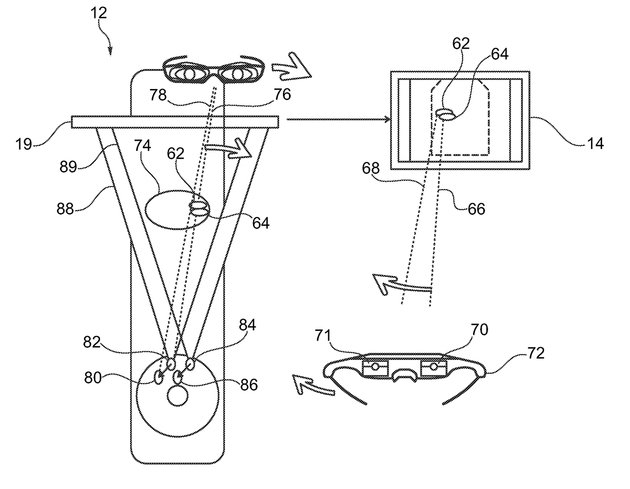
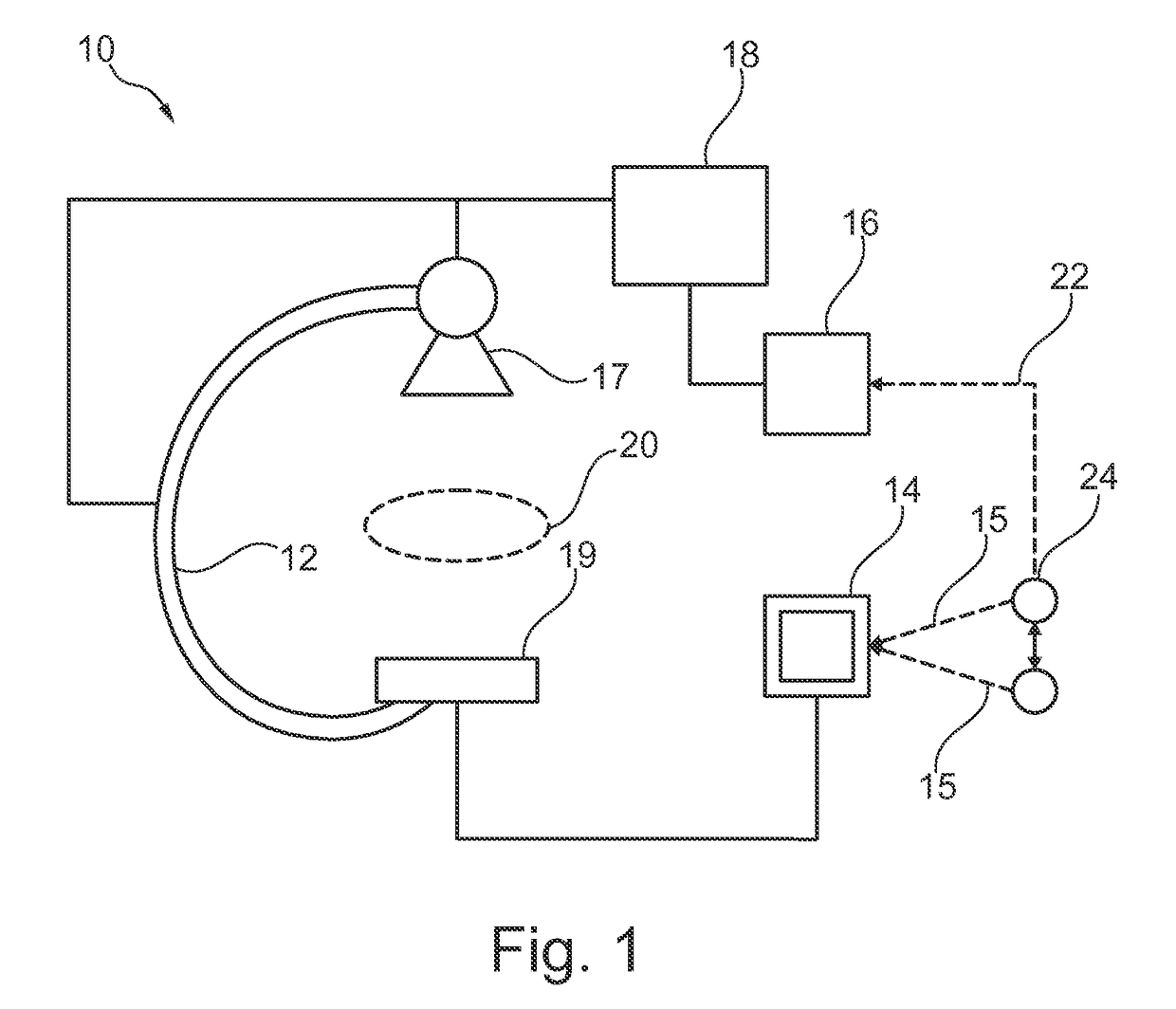
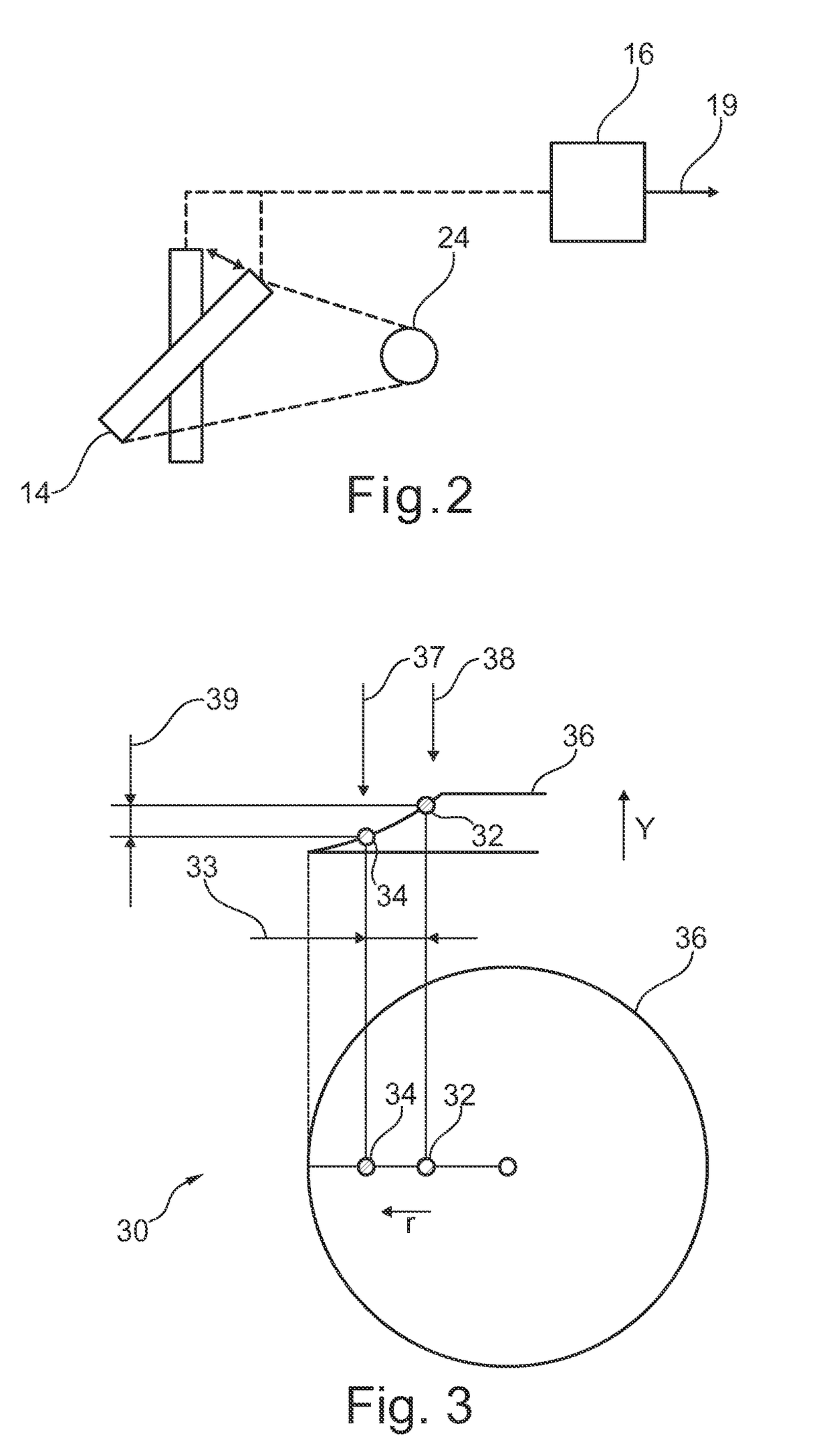
[0049]FIG. 1 describes an X-ray imaging system 10 for providing spatial information of a volume of interest 20 of an object. The X-ray imaging system comprises an image acquisition unit 12, adaption means 18, a user input unit 16, a user input signal 22, a user 24, a viewing direction 15 of a user, and a display unit 14. The image acquisition unit 12 comprises an X-ray source 17 and a detector 19, adapted to generate images of a volume of interest 20. The X-ray source 17 emits X-ray radiation which radiates through the volume of interest 20 and is received at the detector 19. The detector 19 and the X-ray source 17 can be mechanically arranged, for instance using a C-arm. The C-arm of the image acquisition unit 12 can be moved in all dimensions of the room. Instead of a C-arm, any other mechanical means can be used. The movement of the different mechanical components of the image acquisition system is achieved by adapting means 18.

[0050]The adapting means can be motor-driven means t...


PUM


Abstract

An X-ray imaging system includes an x-ray image acquisition unit, a display unit, an input unit, and adapting means. The x-ray image acquisition unit acquires a first image of a volume of interest of an object in a first projection direction and acquires a second image in a second projection direction. The display unit displays the first and the second image. The input unit determines the second projection direction by an input of a user. The user input includes a change in a viewing-direction of the user viewing the first image. The adapting means adapt a spatial relation between the projection direction of the image acquisition unit and the volume of interest of the object such that the projection direction correlates with the second viewing direction.

Description

CROSS REFERENCE TO RELATED APPLICATIONS[0001]This application claims the benefit of International Application Number PCT / IB2013 / 051856, filed Mar. 8, 2013, and U.S. Provisional Application Ser. No. 61 / 615,430, filed Mar. 26, 2012, incorporated herein in whole by reference.FIELD OF THE INVENTION[0002]The present invention relates to providing spatial information of a volume of interest of an object. In particular, the present invention relates to an X-ray imaging system for providing spatial information of a volume of interest of an object, a method for X-ray imaging for providing spatial information of an object, a computer program element, and a computer readable medium.BACKGROUND OF THE INVENTION[0003]During medical interventions, medical staff is often required to change the projection direction of an imaging system while performing medical actions at the patient, for instance during a surgery. Modern imaging equipment allows to generate images from different directions. In parti...

Claims


Application Information

Patent Timeline
Patent Type & Authority Patents(United States)
IPC IPC(8): A61B6/02A61B6/00G06F3/01
CPCA61B6/463A61B6/022A61B6/4007A61B6/4028A61B6/462A61B6/545A61B6/4441G06F3/011
Inventor JACOBS, JOHANNES WILHELMUS MARIAKREMER, FRANS HENKSTEINHAUSER, HEIDRUN
Owner KONINKLIJKE PHILIPS ELECTRONICS NV
Why Eureka
Try Eureka