Multi-speed transmission in planetary design

a multi-speed transmission and planetary design technology, applied in mechanical equipment, transportation and packaging, gearing, etc., can solve the problem of limited axial installation space available, and achieve the effect of good gearing efficiency and easy access to shifting elements

Inactive Publication Date: 2017-04-11
ZF FRIEDRICHSHAFEN AG
View PDF11 Cites 1 Cited by
  • Summary
  • Abstract
  • Description
  • Claims
  • Application Information

AI Technical Summary

Benefits of technology

[0007]Given the fact that the first shaft, as a drive, is detachably connected or connectable to the sun gear of the third planetary gear set, to the planetary gear carrier of the second planetary gear set, to the planetary gear carrier of the third planetary gear set, and is connectable or connected to the sun gear of the first planetary gear set, and that the second shaft, as an output, is connected, or is detachably connected or connectable, to the first machine element and to the second machine element, a multi-speed transmission in accordance with the invention that enables an actuation of the shifting elements that improves the degree of efficiency and is thus in line with demand arises. The advantageously low number of transmission elements of the multi-speed transmission for a front-transverse design has its transmission elements nested with each other in such a manner that an arrangement that particularly saves axial installation space is enabled. In addition to the improved degree of efficiency, low component stresses and low construction costs arise.
[0008]The easy accessibility of the shifting elements may be realized, among other things, on the one hand through the use of brakes as shifting elements and, on the other hand, through the use of clutches as shifting elements, which are preferentially positioned at outside shafts, preferably at the drive and at the output, with the multi-stage transmission in accordance with the invention. Due to the low construction costs, in an advantageous manner, low production costs and a low weight of the multi-speed transmission in accordance with the invention arise.

Problems solved by technology

However, with a front-transverse installation of the transmission in a vehicle, only a limited axial installation space is available.

Method used


Image

  • Multi-speed transmission in planetary design
  • Multi-speed transmission in planetary design
  • Multi-speed transmission in planetary design

Examples


Embodiment Construction

[0024]Reference will now be made to embodiments of the invention, one or more examples of which are shown in the drawings. Each embodiment is provided by way of explanation of the invention, and not as a limitation of the invention. For example features illustrated or described as part of one embodiment can be combined with another embodiment to yield still another embodiment. It is intended that the present invention include these and other modifications and variations to the embodiments described herein.

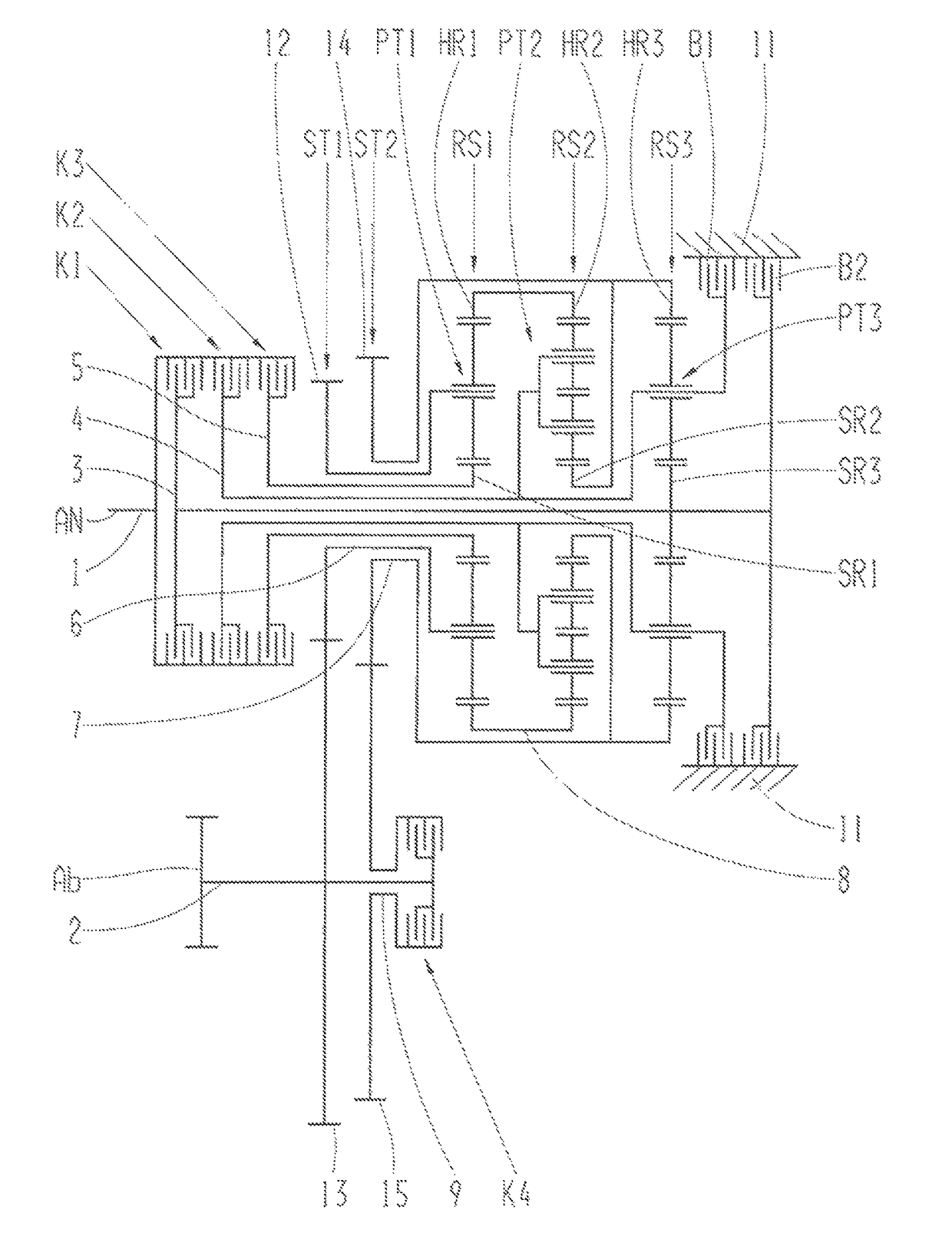
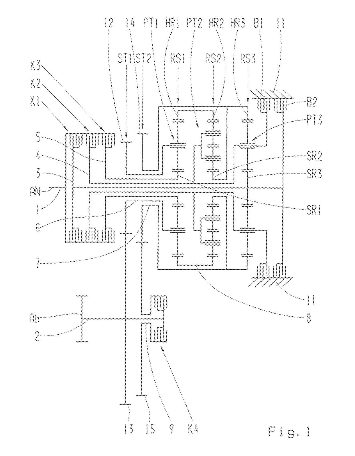
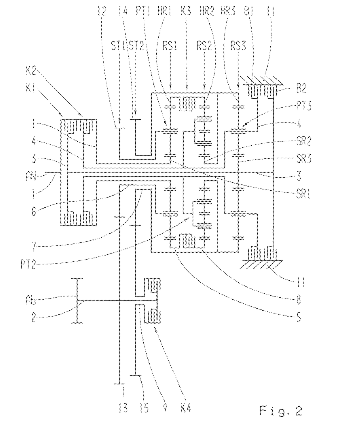
[0025]Each of FIGS. 1 to 6 shows an example of a design variant of the multi-speed transmission in planetary design in accordance with the invention, for example as an automatic gearbox or automatic transmission, for a vehicle, for which varying arrangement positions of the third shifting element designed as a clutch are shown.

[0026]Regardless of the particular design variants, the multi-speed transmission comprises a merely schematically indicated housing 11, with a first shaft 1 ...


PUM


Abstract

A multi-speed transmission in planetary design for a vehicle with a housing includes a first shaft provided as a drive and a second shaft provided as an output that is arranged axially parallel to the drive. Three planetary gear sets and additional shafts along with six shifting elements are provided, through which the actuation of several gears are realized. Machine elements are provided for the transfer of torque between the drive and the output. The first shaft is connectable, as a drive, to the sun gear of the third planetary gear set, to the planetary gear carrier of the second planetary gear set, to the planetary gear carrier of the third planetary gear set, and is connectable or connected to the sun gear of the first planetary gear set. The second shaft is connected or connectable, as a drive, to the first machine element and to the second machine element.

Description

FIELD OF THE INVENTION[0001]The present invention relates to a multi-speed transmission in planetary design for a vehicle.BACKGROUND[0002]As an example, publication DE 10 2007 014 150 A1 discloses a load-shiftable multi-speed transmission. With the multi-speed transmission, the drive shaft is firmly connected through a torsional vibration damper to a first shaft of a first shaft train. A second shaft train arranged parallel to this includes, among other things, the two output shafts designated as shafts. The two shaft trains are connected to each other through three spur gear stages. A first three-shaft planetary gear stage is located on the first shaft train. A second planetary gear stage and a third planetary gear stage are located on the second shaft train. Thus, the multi-speed transmission comprises ten shafts that are connected to each other through three spur gear stages and three planetary gear stages. For shifting the eight forward gears and one reverse gear, five shifting ...

Claims


Application Information

Patent Timeline
Patent Type & Authority Patents(United States)
IPC IPC(8): F16H3/66F16H3/44
CPCF16H3/66F16H3/666F16H2003/445F16H2200/0065F16H2200/0069F16H2200/201F16H2200/2046
Inventor BECK, STEFANSIBLA, CHRISTIANRIEGER, WOLFGANG
Owner ZF FRIEDRICHSHAFEN AG
Why Eureka
Try Eureka