Absolute encoder scale configuration with unique coded impedance modulations

a technology of encoder scale and encoder, which is applied in the direction of instruments, measurement devices, magnitude/direction of magnetic fields, etc., can solve the problems of limited accuracy or resolution, the length of absolute scale that can be extended to for a given scale width

Active Publication Date: 2017-04-11
MITUTOYO CORP
View PDF26 Cites 9 Cited by
  • Summary
  • Abstract
  • Description
  • Claims
  • Application Information

AI Technical Summary

Problems solved by technology

While the '813 patent provides improved winding configurations, the length that the absolute scale can be extended to for a given scale width and accuracy or resolution remains limited (e.g., due in part to limitations for the fabrication accuracy and signal interpolation of such readheads).

Method used


Image

  • Absolute encoder scale configuration with unique coded impedance modulations
  • Absolute encoder scale configuration with unique coded impedance modulations
  • Absolute encoder scale configuration with unique coded impedance modulations

Examples


Embodiment Construction

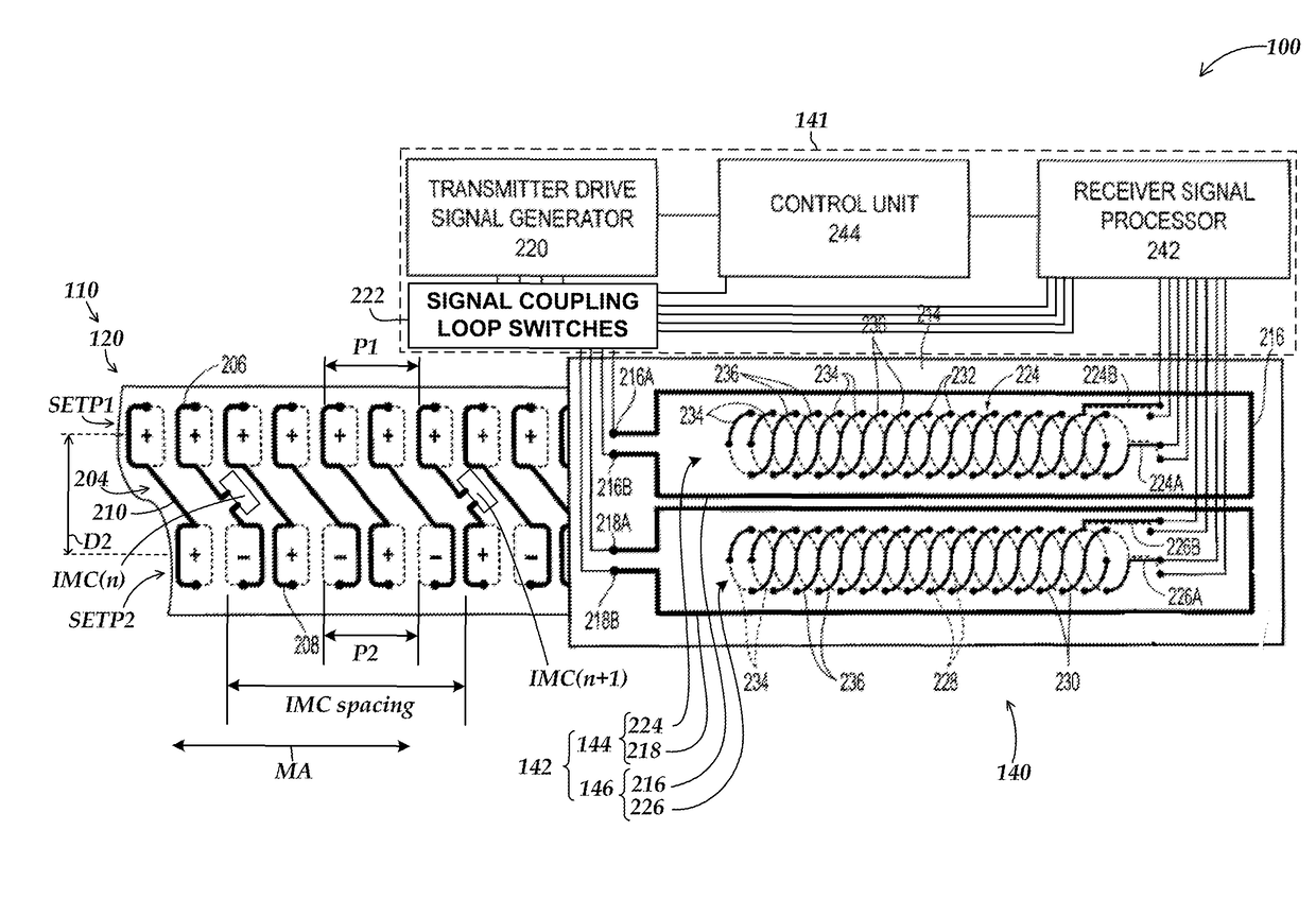
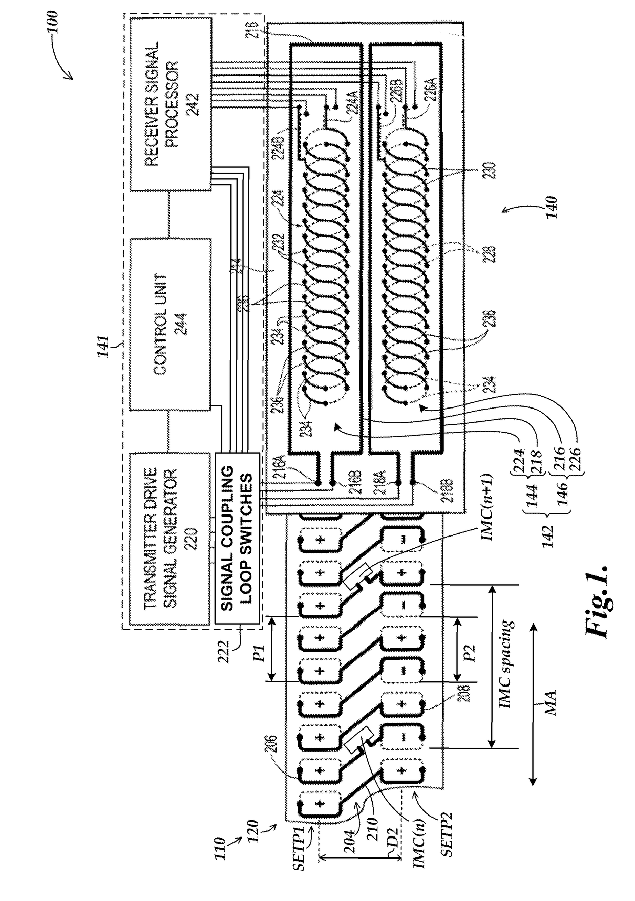
[0014]FIG. 1 is a diagram of a position encoder 100 including a first exemplary implementation of an absolute scale configuration 120 with impedance modulating circuits IMC. The absolute scale configuration 120 is provided on a scale 110 of the position encoder, and a readhead 140 of the position encoder is movable relative to the scale along a measuring axis MA of the scale. The readhead 140 includes a readhead processor 141 and a spatially modulated signal coupling configuration 142. The spatially modulated signal coupling configuration 142 includes a first spatially modulated signal coupling configuration 144 comprising windings 218 and 224 and a second spatially modulated signal coupling configuration 146 comprising windings 216 and 226, located on a substrate 214. The absolute scale configuration 120 includes a plurality of scale loops 204 which include signal coupling loop portions 206 and 208 distributed periodically along the measuring axis MA.

[0015]As will be described in m...


PUM


Abstract

An absolute scale configuration is provided for use in a position encoder which includes a readhead and a scale. The absolute scale configuration includes a plurality of scale loops distributed along a measuring axis to provide a position dependent signal that varies depending on a relative position between the scale loops and the readhead. At least some of the scale loops are coupled to respective impedance modulating circuits connected to receive energy from current induced in the scale loop and to provide a unique coded modulation of the scale loop impedance during a code signal generating state. The unique coded modulations as sensed by the readhead are indicative of a coarse resolution absolute position, which may be utilized in combination with the position dependent signal to determine an absolute position with a high resolution.

Description

BACKGROUNDTechnical Field[0001]The present disclosure relates generally to precision metrology, and more particularly to induced current linear and rotary absolute position encoders.Description of the Related Art[0002]Induced current position encoders typically have a readhead that is movable relative to a scale member, and includes one or more transducers comprising an excitation winding and receiver winding(s). The receiver winding(s) may have a wavelength which is different for different transducers. Each transducer will have a scale or track on the scale member which includes a plurality of flux modulators. The flux modulators may each have a length along the measuring axis that is equal to one-half of the wavelength of the corresponding receiver winding(s).[0003]U.S. Pat. No. 6,329,813, which is commonly assigned and hereby incorporated herein by reference in its entirety, discloses an absolute position encoder transducer with improved winding configurations which increase the ...

Claims


Application Information

Patent Timeline
Patent Type & Authority Patents(United States)
IPC IPC(8): G01R33/02G01D5/20
CPCG01D5/2053
Inventor NAHUM, MICHAEL
Owner MITUTOYO CORP
Why Eureka
Try Eureka