Vibrating element

a technology of vibrating elements and vibrations, which is applied in the direction of diaphragm construction, electromechanical transducers, transducer diaphragms, etc., can solve the problems of poor sound quality performance, distortion, and deformation of the speaker unit frequency response, and achieve the effect of improving the sound quality of the vibrating elemen

Inactive Publication Date: 2017-04-11
COTRON
View PDF19 Cites 4 Cited by
  • Summary
  • Abstract
  • Description
  • Claims
  • Application Information

AI Technical Summary

Benefits of technology

[0025]According to the above descriptions, in the invention, by configuring the stiffening layer of the vibrating element, the influence of the voice coil and the two ends thereof on sound quality presented when the diaphragm vibrates is decreased, such that the sound quality of the vibrating element has a better performance.

Problems solved by technology

Therefore, the voice coil crossing over the diaphragm severely influences vibration of the diaphragm, such that frequency response of the speaker unit is degraded, which leads to a poor sound quality performance.
However, the connection points of the two ends 25 of the voice coil 20 obviously spoil vibration consistency of such area, such that the distortion is increased and the sound quality if deteriorated.

Method used


Image

  • Vibrating element
  • Vibrating element
  • Vibrating element

Examples


Embodiment Construction

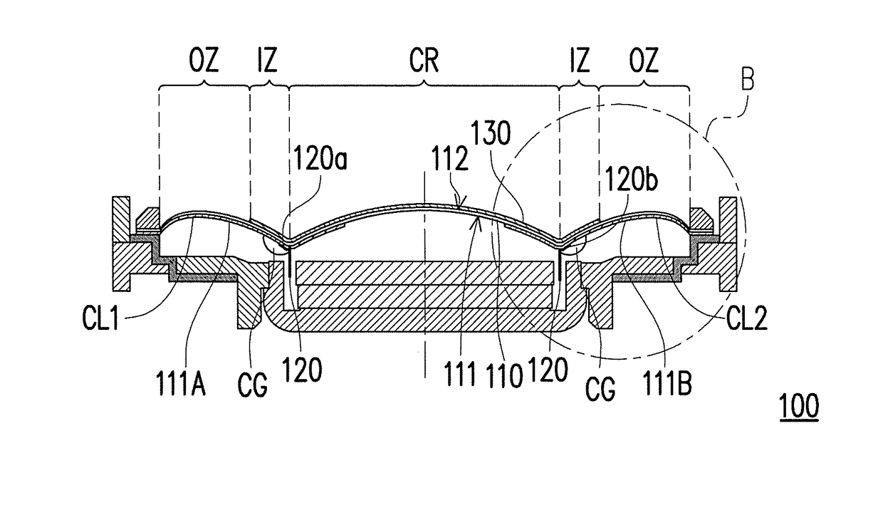
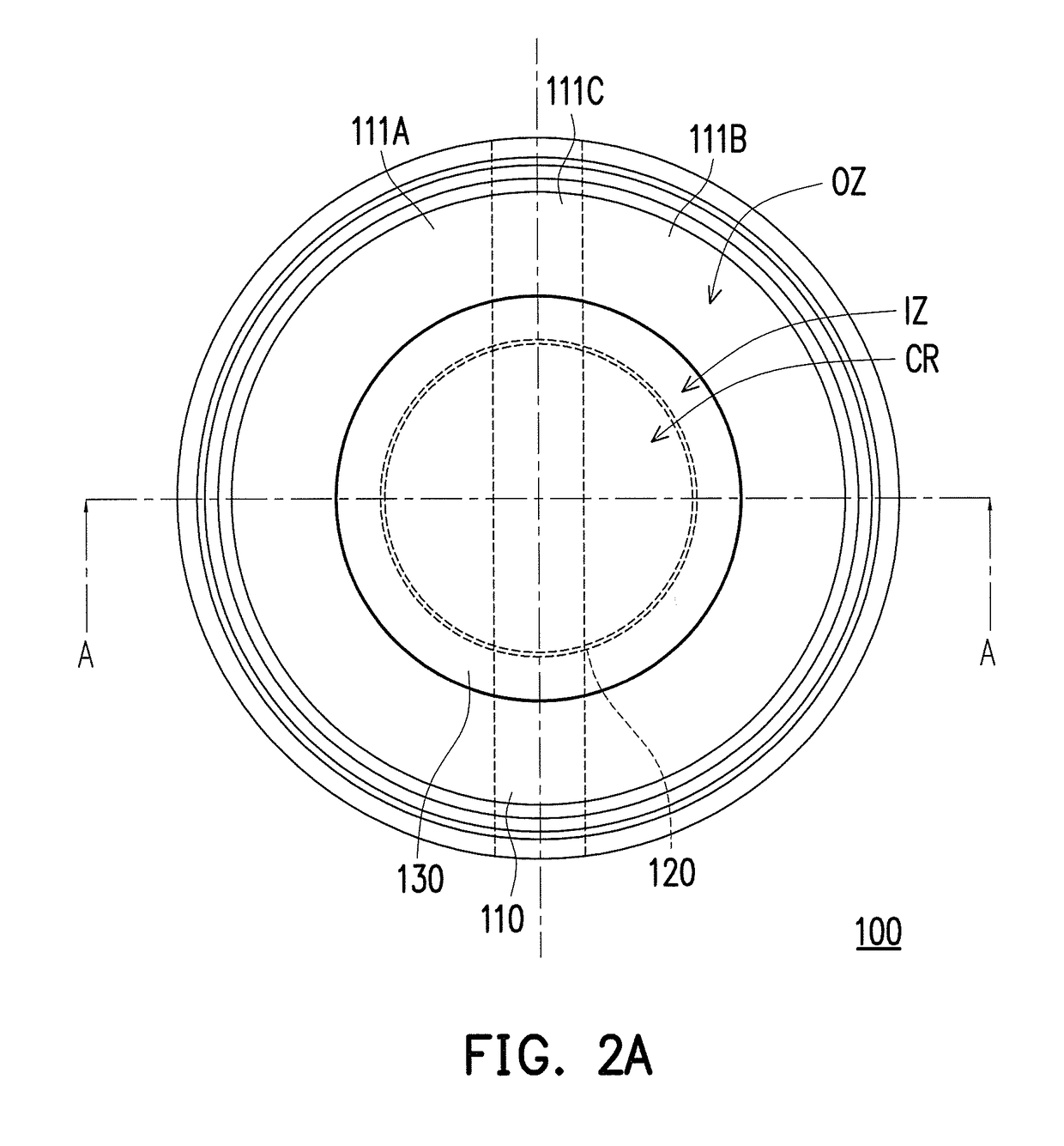
[0048]FIG. 2A is a front view of a vibrating element according to an embodiment of the invention. FIG. 2B is a cross-sectional view of the vibrating element of FIG. 2A along a section line A-A. FIG. 2C is an enlarged view of a partial area B of FIG. 2B. Referring to FIG. 2A, FIG. 2B and FIG. 2C, the vibrating element 100 of the invention includes a diaphragm 110, a voice coil 120 and a stiffening layer 130. For example, in the present embodiment, the diaphragm 110 has a first surface 111 and a second surface 112 opposite to each other, where the first surface 111 includes a first conductive region 111A and a second conductive region 111B separated from each other. In detail, in the present embodiment, the first conductive region 111A and the second conductive region 111B are separated by a linear non-conductive region 111C, and the first conductive region 111A and the second conductive region 111B respectively present a shape similar to a semicircle, though the invention is not limi...


PUM


Abstract

A vibrating element including a diaphragm, a voice coil and a stiffening layer is provided. The diaphragm has a first surface and a second surface opposite to each other. The first surface includes a first conductive region and a second conductive region. The voice coil is disposed on the first surface. Two ends of the voice coil are electrically connected to the first conductive region and the second conductive region. The stiffening layer is disposed on the diaphragm. The diaphragm has a center region, which is enclosed and circled by the voice coil and includes an area of the diaphragm above the voice coil. The region outside the center region includes an inner circled zone and an outer circled zone surrounding the inner circled zone. At least one end of the voice coil is located in the inner circled zone and the stiffening layer covers the inner circled zone.

Description

CROSS-REFERENCE TO RELATED APPLICATION[0001]This application claims the priority benefit of Taiwan application serial no. 103118434, filed on May 27, 2014. The entirety of the above-mentioned patent application is hereby incorporated by reference herein and made a part of this specification.BACKGROUND[0002]Technical Field[0003]The invention relates to a vibrating element, and particularly relates to a vibrating element adapted for a speaker unit.[0004]Related Art[0005]Along with development of technology, electronic products are developed towards a trend of miniaturization, and people can use the miniaturized electronic products, for example, radios, walkmans, etc., at anytime anywhere. Moreover, as personal digital products are gradually popularised, the commonly used MP3, mobile phones, personal digital assistants (PDAs) or notebooks, etc. become indispensable in daily life. Moreover, smart phones capable of providing various audio and video entertainments are more popular product...

Claims


Application Information

Patent Timeline
Patent Type & Authority Patents(United States)
IPC IPC(8): H04R25/00H04R9/04H04R9/06H04R7/12H04R7/26H04R1/06H04R7/02
CPCH04R9/046H04R7/122H04R7/125H04R7/26H04R9/06H04R1/06H04R7/02H04R2307/027H04R2307/201
Inventor YANG, BILL
Owner COTRON
Why Eureka
Try Eureka