
Geometrically constrained slope control system for cylinder construction equipment

a technology of geometries and construction equipment, applied in the field of paving machines, can solve the problems of large paving machines, high cost of systems, and difficult to accurately control the slope of paving machines, and achieve the effect of reducing errors and accurate slope control

Active Publication Date: 2017-04-18
GOMACO
View PDF5 Cites 6 Cited by
  • Summary
  • Abstract
  • Description
  • Claims
  • Application Information

AI Technical Summary

Benefits of technology

The patent text describes a method for controlling a vehicle's movement based on its current position and the shape of the track it is running on. The method uses sensors to measure the track's position and applies corrections in real-time to ensure accurate movement. By doing so, the system becomes more responsive and can handle poor track conditions. The sensors can be associated with specific legs to reduce errors, and multiple sensors can be used to increase accuracy without adding more sensors. The technical effect of this method is a more efficient and reliable control system for accurate slope control.

Problems solved by technology

However, paving machines are large and often operate in hostile environments.
Constantly monitoring and adjusting the orientation of a paving machine for the proper long slope and cross-slope is a laborious process.
Systems exist to control the linear movement of paving machines with a high degree of precision, however those systems often only provide a single reference point which is insufficient for locating the machine in three dimensions.
Alternatively, surveying equipment may adequately define the location and orientation of a machine in space, but such systems are very expensive (in initial capital investment but more so in high skilled labor cost to operate on a daily basis).

Method used


Image

  • Geometrically constrained slope control system for cylinder construction equipment
  • Geometrically constrained slope control system for cylinder construction equipment
  • Geometrically constrained slope control system for cylinder construction equipment

Examples


Embodiment Construction

[0023]Reference will now be made in detail to the subject matter disclosed, which is illustrated in the accompanying drawings. The scope of the invention is limited only by the claims; numerous alternatives, modifications and equivalents are encompassed. For the purpose of clarity, technical material that is known in the technical fields related to the embodiments has not been described in detail to avoid unnecessarily obscuring the description.

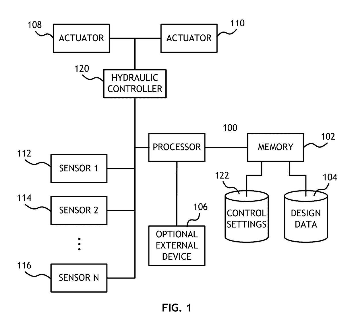
[0024]Referring to FIG. 1, a block diagram of a computer system useful for implementing embodiments of the present invention is shown. The computer system, embodied in a paving machine, may include a processor 100 configured to execute computer executable program code stored in a memory 102 connected to the processor 100. A desired paving profile, or some other data defining the desired movement and orientation of the construction machine, may be stored in a data storage element 104 also connected to the processor 100, potentially through the...


PUM


Abstract

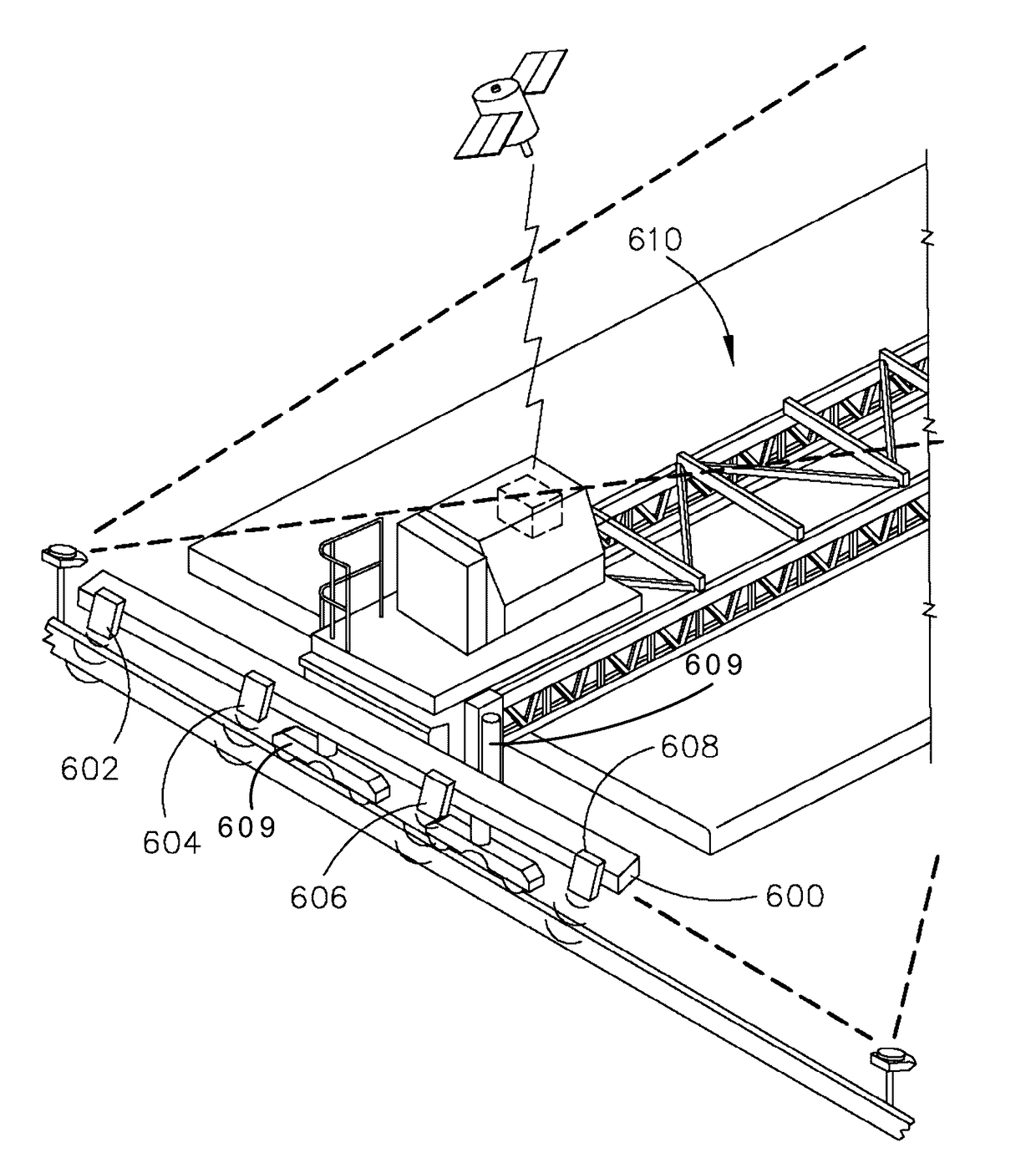
A computer control system in a paving machine determines a location, long slope (pitch), cross-slope (roll), and elevation (with respect to reference surface) of the machine with reference to a plurality of sensors. The long slope, cross slope and elevation are compared to values from a design surface (horizontal alignment, vertical profile, and cross sections) using the location of the machine to query the design data. Deviations from measured orientation and elevation to the design (desired values) are determined for each elevation cylinder of the paving machine based on the sensor data using constrained geometric control algorithms that predict future deviations. Corrections are applied to bring the actual location, long slope, cross-slope and elevation to within acceptable tolerances of the desired values. Sensors are associated with specific legs, with some sensors associated with more than one leg, such that sensor values may be averaged to reduce error.

Description

PRIORITY[0001]The present application claims the benefit under 35 U.S.C. §119(e) of U.S. Provisional Application Ser. No. 61 / 891,131, filed Oct. 15, 2013, which is incorporated herein by reference.FIELD OF THE INVENTION[0002]The present invention is directed generally toward paving machines and more particularly toward systems for controlling the slope of a paving machine.BACKGROUND OF THE INVENTION[0003]Paving machines, and construction machines in general, require substantial in movement and orientation to produce the desired outcome. Especially in regards to paving machines, long slope and cross-slope of the machine must be controlled within very tight tolerances. However, paving machines are large and often operate in hostile environments. Constantly monitoring and adjusting the orientation of a paving machine for the proper long slope and cross-slope is a laborious process.[0004]Systems exist to control the linear movement of paving machines with a high degree of precision, how...

Claims


Application Information

Patent Timeline
IPC IPC(8): E01C19/00
CPCE01C19/00E01C2301/00E01C19/004E01C19/006E01C19/42
Inventor SCHAEDING, CHAD
Owner GOMACO
Learn More