Connection terminal structure

a terminal and connection technology, applied in the direction of fastening means, electrical equipment, mechanical equipment, etc., can solve the problems of high cost, difficult shaping, and complex structure, and achieve the effects of low cost, simple assembly process, and convenient shaping

Active Publication Date: 2017-04-18
DINKLE ENTERPRISE CO LTD
View PDF13 Cites 12 Cited by
  • Summary
  • Abstract
  • Description
  • Claims
  • Application Information

AI Technical Summary

Benefits of technology

[0009]Given the aforesaid structural design, the connection terminal structure is characterized advantageously by structural simplicity, ease of shaping, low costs, and a simple assembly process.

Problems solved by technology

However, the conventional connection terminal structure is characterized disadvantageously by structural complexity, difficulty in shaping, high costs, and an intricate assembly process.

Method used


Image

  • Connection terminal structure
  • Connection terminal structure
  • Connection terminal structure

Examples


Embodiment Construction

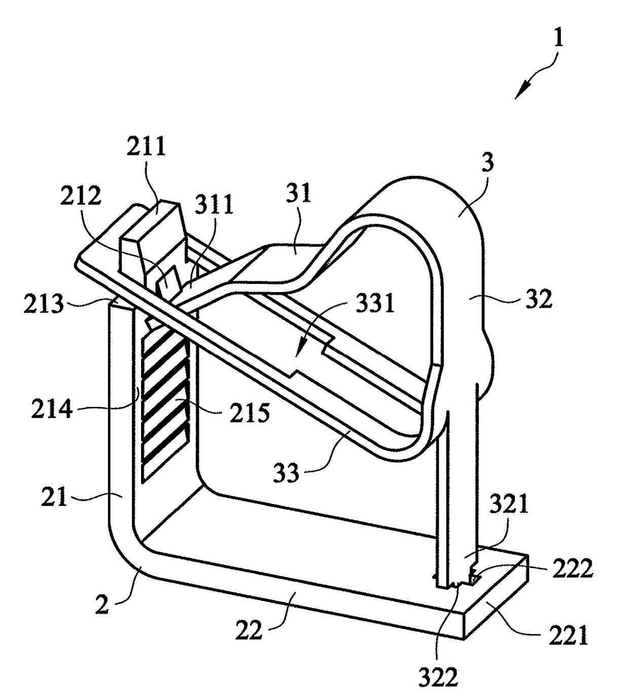
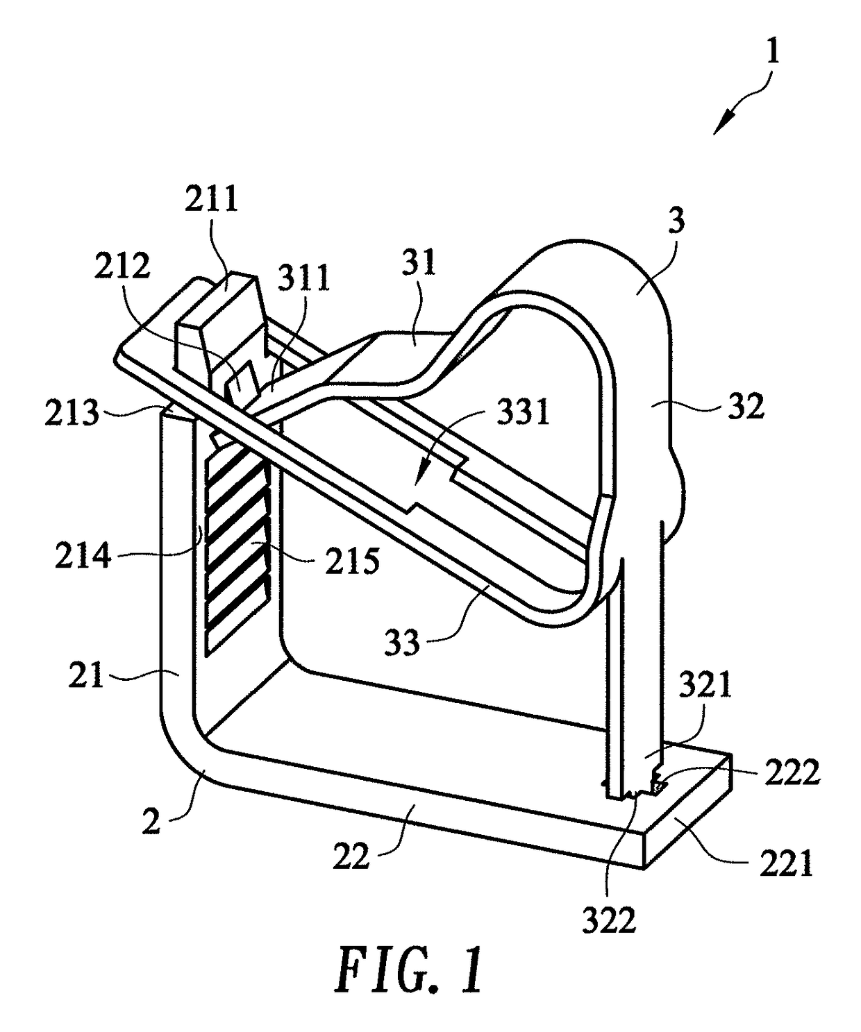
[0020]FIG. 1 is a perspective view according to the first preferred embodiment of the present invention.

[0021]Referring to FIG. 1, a connection terminal structure 1 comprises a basic element 2 and a clamping element 3. The basic element 2 is bent to be L-shaped and comprises a longitudinal arm 21 and a transverse arm 22 connected to the longitudinal arm 21. An upper end 211 of the longitudinal arm 21 forms an engaging flange 212 and an engaging shoulder portion 213. A right end 221 of the transverse arm 22 forms a joint portion 222. The clamping element 3 comprises a resilient clamping arm 31, a supporting arm 32, and a connecting arm 33. The connecting arm 33 forms an opening portion 331. The connecting arm 33 extends from the supporting arm 32 to the longitudinal arm 21. The opening portion 331 of the connecting arm 33 fits around and engages with the engaging shoulder portion 213 of the longitudinal arm 21. A lower end 321 of the supporting arm 32 forms a joint end 322. The joint...


PUM


Abstract

A connection terminal structure includes a basic element and a clamping element. The basic element is bent to be L-shaped and includes a longitudinal arm and a transverse arm connected to the longitudinal arm. An upper end of the longitudinal arm forms an engaging flange and an engaging shoulder portion. A right end of the transverse arm forms a joint portion. The clamping element comprises a resilient clamping arm, a supporting arm, and a connecting arm. The connecting arm forms an opening portion and extends from the supporting arm to the longitudinal arm. The opening portion fits around the engaging shoulder portion. A lower end of the supporting arm forms a joint end jointed to the joint portion. The resilient clamping arm connects with the supporting arm, extends to the longitudinal arm, has a front end engaging with the engaging flange, and penetrates the opening portion to move resiliently.

Description

BACKGROUND OF THE INVENTION[0001]1. Technical Field[0002]The present invention relates to connection terminal structures, and more particularly, to a connection terminal structure characterized advantageously by structural simplicity, ease of shaping, low costs, and a simple assembly process.[0003]2. Description of Related Art[0004]A conventional connection terminal structure for use with a typical electronic device is adapted to build an electrical connection whereby different electronic components disposed in the electronic device are electrically connected.[0005]For instance, a conventional connection terminal structure comprises an insulating case and a connection clamp disposed therein. The connection clamp has a resilient clamping arm. To build an electrical connection, an electrical wire is passed through a through-hole of the insulating case to reach the connection clamp and drive the resilient clamping arm to move. Then, the electrical wire is clamped by the connection clam...

Claims


Application Information

Patent Timeline
Patent Type & Authority Patents(United States)
IPC IPC(8): H01R4/26H01R11/20H01R4/48F16B2/22H01R11/00
CPCF16B2/22H01R4/26H01R4/48H01R11/00H01R11/20F16B2/10H01R4/48365
Inventor WU, SHANG TSAI
Owner DINKLE ENTERPRISE CO LTD
Why Eureka
Try Eureka