
Hybrid temporary anchorage device implant system and associated methods

a temporary anchorage device and implant system technology, applied in the field of orthodontic implants, can solve the problems of inability to easily remove, more expensive root form implants than tads, etc., and achieve the effect of reducing the length of the second abutment and the size of the first abutmen

Active Publication Date: 2017-04-25
OUELLETTE PAUL
View PDF5 Cites 4 Cited by
  • Summary
  • Abstract
  • Description
  • Claims
  • Application Information

AI Technical Summary

Benefits of technology

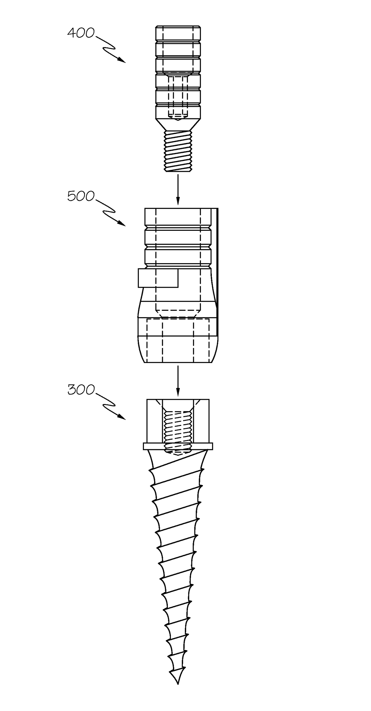
The present invention provides a hybrid temporary anchorage device implant system that can mechanically integrate or "fibro-osseointegrate" with a dental implant, but not biologically or "permanently" integrate, making it easy to remove. This system can act as a "placeholder" implant that can be easily backed out of a patient's jawbone tissue to be replaced by a full-size implant as required. It can also preserve cortical bone and crestal bone, eliminating the need for expensive and painful future bone grafting procedures. This system can assist with emergence profile development, tissue sculpting and socket forming, as well as orthodontic tooth movement. Additionally, it can be used for several months to several years to attach an abutment and temporary crown. The method involves attaching a titanium abutment to a TAD implant, preparing an osteotomy, inserting the TAD implant, and fitting a second abutment over the first abutment.

Problems solved by technology

TADs all mechanically integrate, but do not integrate to the point that they cannot be easily removed.
Root form implants are more expensive than TADs.
As a result of the expense of root form implants, oftentimes patients wait years between a tooth extraction and the implantation of a root form implant while they save up their money for the procedure.

Method used


Image

  • Hybrid temporary anchorage device implant system and associated methods
  • Hybrid temporary anchorage device implant system and associated methods
  • Hybrid temporary anchorage device implant system and associated methods

Examples


Embodiment Construction

[0023]The present invention will now be described fully hereinafter with reference to the accompanying drawings, in which preferred embodiments of the invention are shown. Like numbers refer to like elements throughout. This invention may, however, be embodied in many different forms and should not be construed as limited to the embodiments set forth herein. Rather, these embodiments are provided so that this disclosure will be thorough and complete, and will fully convey the scope of the invention to those skilled in the art. Those of ordinary skill in the art will realize that the following embodiments of the present invention are only illustrative and are not intended to be limiting in any way. Other embodiments of the present invention will readily suggest themselves to such skilled persons having the benefit of this disclosure. Illustrative embodiments will now be described more fully herein with reference to the accompanying drawings, in which embodiments are shown. This discl...


PUM


Abstract

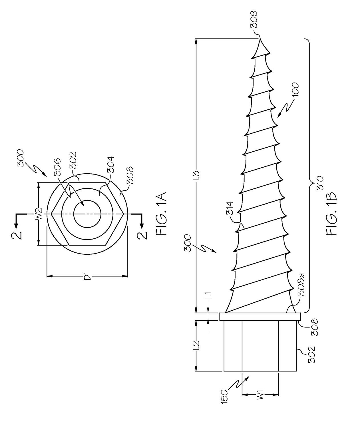
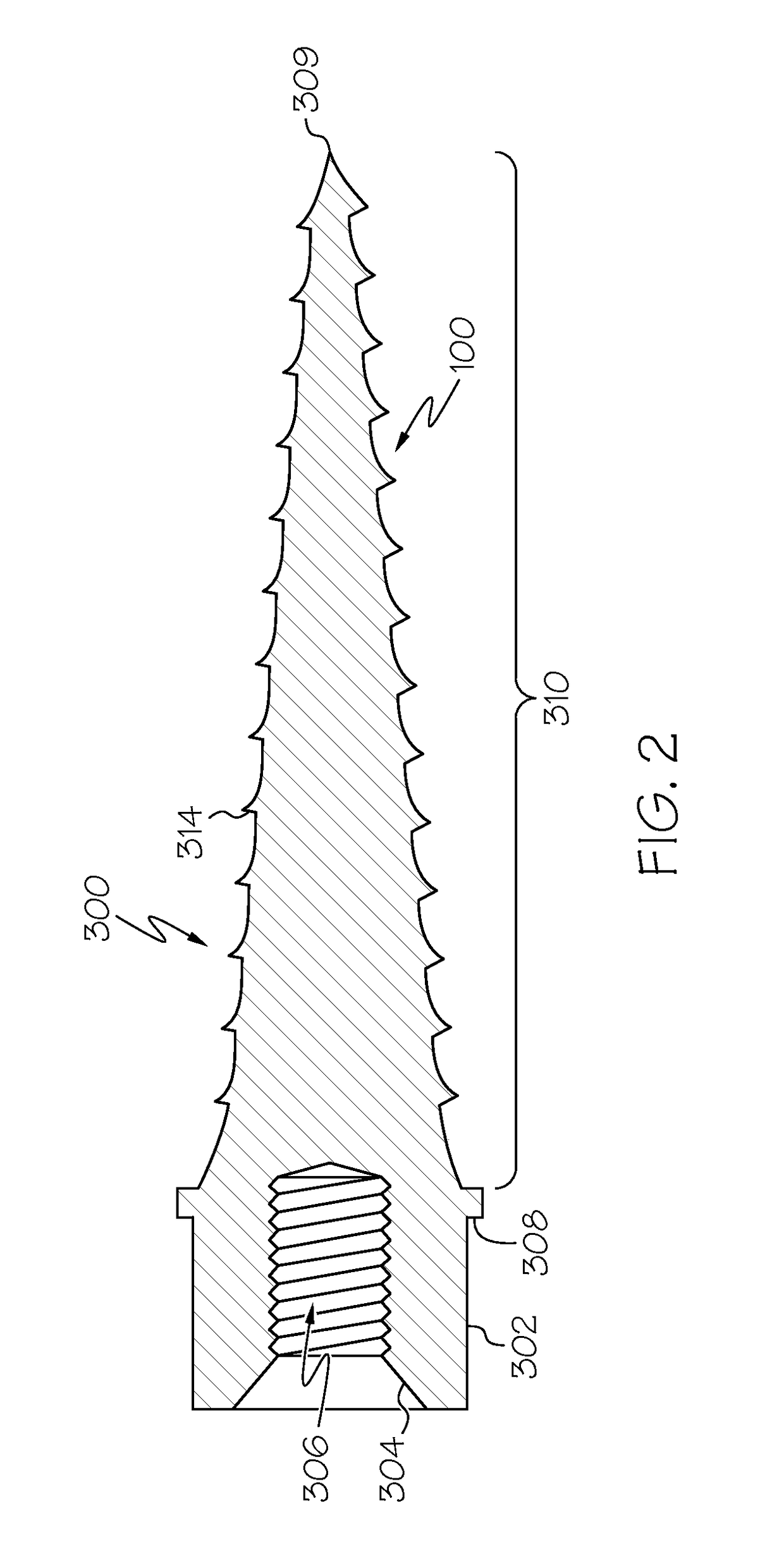
A hybrid temporary anchorage device implant system and method of use is disclosed. A temporary anchorage device (TAD) implant includes an external hex head, a cupped inner portion, a threaded core, a platform, and an implant portion. A first abutment is installed on the implant portion. The first abutment may include a graduated portion, a screw-retained healing collar, and a threaded portion. A second abutment may be installed over the first abutment. The second abutment may include a graduated head, a bulbous base, and an inner canal.

Description

CROSS-REFERENCE TO RELATED APPLICATION[0001]The present patent document claims the benefit of the filing date of U.S. patent application Ser. No. 61 / 832,261, filed Jun. 7, 2013, the disclosure of which is incorporated herein by reference.FIELD OF THE INVENTION[0002]The present invention relates to the field of orthodontic implants and, more specifically, to the field of hybrid temporary anchorage device implants for both short term use and long term use.BACKGROUND OF THE INVENTION[0003]It is well known that temporary anchorage devices (TADs) have been used for years in orthodontic therapy to attempt to overcome the limitations of conventional orthodontic anchorage devices. A provisional implant or TAD is a device that is temporarily fixed to bone for the purpose of enhancing orthodontic anchorage either by supporting a tooth or group of teeth acting as anchorage during movement of another tooth or group of teeth, or by obviating the need to use a tooth or a group of teeth as anchora...

Claims


Application Information

Patent Timeline
Patent Type & Authority Patents(United States)
IPC IPC(8): A61C8/00
CPCA61C8/0024A61C8/006A61C8/0068A61C8/0069A61C8/0078A61C8/0096A61C7/00A61C8/00A61C8/0012A61C13/0001A61C2008/0084A61C2201/005
Inventor OUELLETTE, PAUL
Owner OUELLETTE PAUL
Learn More