Image projection system and image projection method

a projection system and image technology, applied in the field of image projection system and image projection method, can solve the problems of increasing the production cost of the optical printing device, increasing the size of the entire optical printing device, and increasing the size of the image projection system

Inactive Publication Date: 2017-04-25
ROLAND DG CORP
View PDF7 Cites 17 Cited by
  • Summary
  • Abstract
  • Description
  • Claims
  • Application Information

AI Technical Summary

Problems solved by technology

However, provision of such a mechanism that adjusts the position or the posture of a projector increases the size of the image projection system.
This increases the size of the entirety of the optical printing device including the image projection system mounted thereon, and also raises the production cost of the optical printing device.
In this situation, an image projection system capable of performing appropriate projection without a mechanism as described above has been desired, but has not been developed so far.

Method used


Image

  • Image projection system and image projection method
  • Image projection system and image projection method
  • Image projection system and image projection method

Examples


Embodiment Construction

[0050]Hereinafter, examples of preferred embodiments of an image projection system and an image projection method according to the present invention will be described.

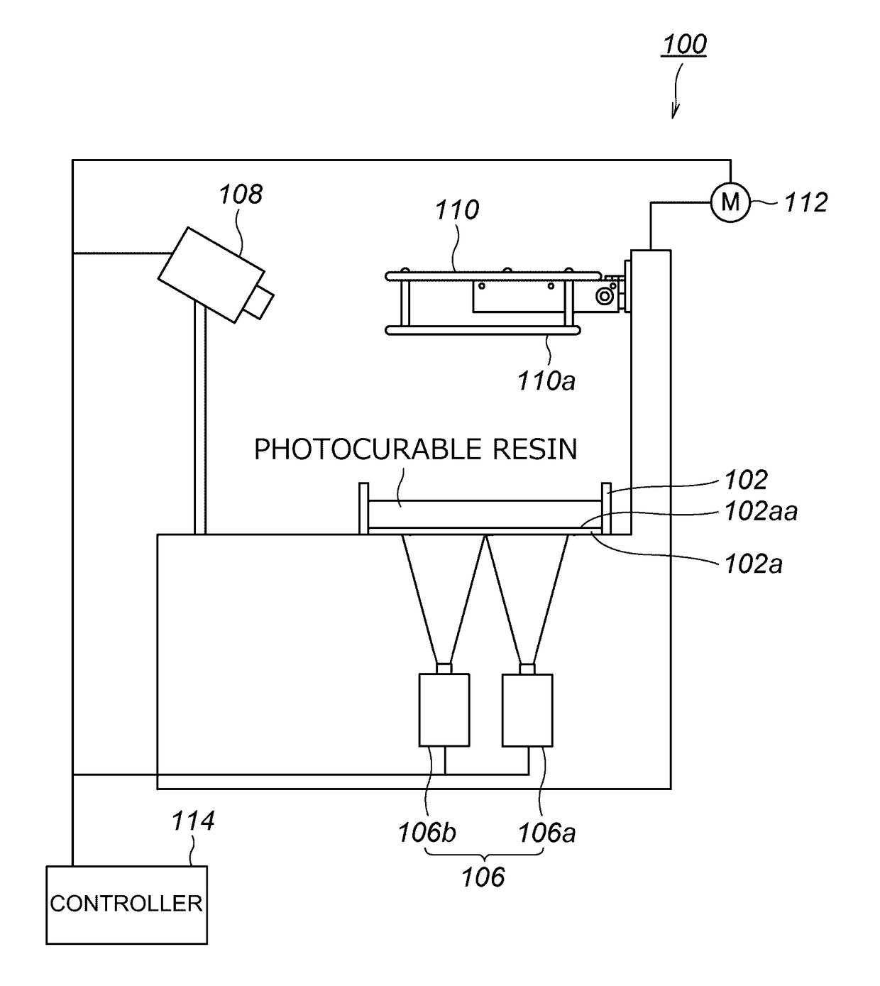
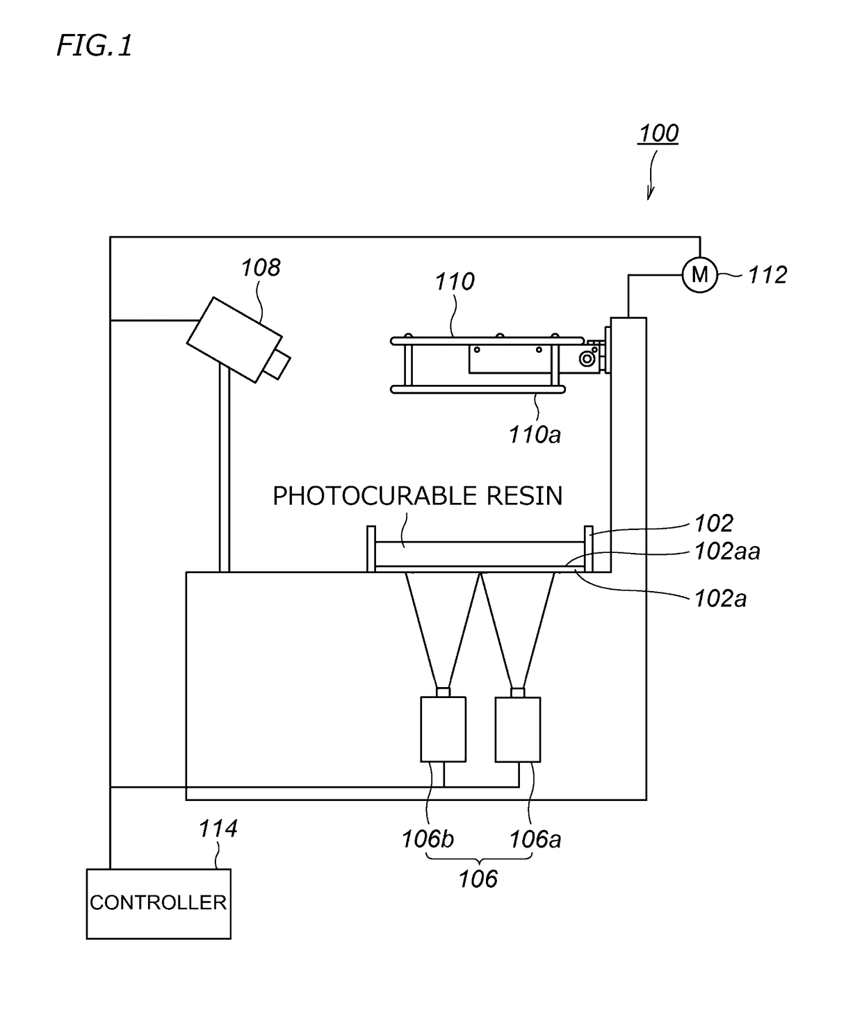
[0051]As shown in FIG. 1, an optical printing device 100 according to a preferred embodiment of the present invention includes a container 102 that accommodates a photocurable resin, projectors (image projection devices) 106 each of which projects an image to a bottom plane 102a of the container 102, a camera (image capturing device) 108 located at a position at which the camera 108 is able to capture an image of the projected image, a printing object holder 110 that holds the photocurable resin cured in the container 102, a driver 112 that moves the printing object holder 110 in an up-down direction, and a controller 114 that controls the camera 108 that captures an image of an image projection area, the projectors 106 and the driver 112.

[0052]The bottom plane 102a of the container 102 includes a light-transmissive pl...


PUM

PropertyMeasurementUnit
lengthaaaaaaaaaa
widthaaaaaaaaaa
sizeaaaaaaaaaa

Abstract

An image projection system includes a second transform matrix calculator that calculates a second projection transform matrix usable to projection-transform first intersection coordinates into intersection coordinates uniformly or substantially uniformly distributed in a first area and calculates a third projection transform matrix usable to projection-transform second intersection coordinates into intersection coordinates uniformly or substantially uniformly distributed in a second area; and an image corrector that transforms image data on a first divided image by use of the second projection transform matrix, transforms image data on a second divided image by use of the third projection transform matrix, and translates at least one of the first divided image and the second divided image toward a borderline between the first divided image and the second divided image to delete a gap between the first divided image and the second divided image.

Description

[0001]The present application claims priority from Japanese Patent Application No. 2014-079588 filed on Apr. 8, 2014, which is incorporated by reference herein in its entirety.BACKGROUND OF THE INVENTION[0002]1. Field of the Invention[0003]The present invention relates to an image projection system and an image projection method.[0004]2. Description of the Related Art[0005]A conventional optical printing device produces a three-dimensional printing object by use of a photocurable resin in a liquid state having a property of being cured by being irradiated with light such as visible light, ultraviolet light or the like. Such an optical printing device uses, for example, a suspension stacking system, by which a three-dimensional printing object is produced by stacking layers of a photocurable resin cured into a predetermined shape. By the suspension stacking system, a three-dimensional printing object is produced as follows. A light-transmissive plate is provided on a bottom surface o...

Claims


Application Information

Patent Timeline
Patent Type & Authority Patents(United States)
IPC IPC(8): G06T5/00B29C67/00G06T7/33G06F17/16G06T3/40B33Y50/02B33Y10/00
CPCG06F17/16B29C67/0062B29C67/0088G06T3/40G06T7/33B33Y10/00B33Y50/02G06T2207/30208B29C64/124B29C64/393
Inventor UEDA, JUNNAKAMURA, YASUTOSHI
Owner ROLAND DG CORP
Why Eureka
Try Eureka