
Image processing device and image capture device performing restoration processing using a restoration filter based on a point spread function

a technology of image processing and restoration processing, applied in the field of image processing device and image capture device according to restoration processing based on a point spread function, can solve the problems of negative influence of image quality excluding point image restoration accuracy, unexpected bad influence of image quality, etc., and achieve excellent reproducibility and high restoration accuracy

Active Publication Date: 2017-04-25
FUJIFILM CORP
View PDF15 Cites 15 Cited by
  • Summary
  • Abstract
  • Description
  • Claims
  • Application Information

AI Technical Summary

Benefits of technology

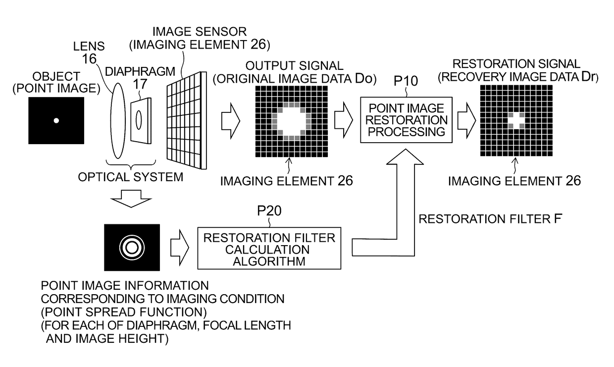
[0009]There are proposed filters of various models as a restoration filter for point image restoration processing, and, for example, a Wiener filter is widely known. Since conventional restoration filters such as this Wiener filter and the restoration filters of PTL 1 are filters designed for the purpose of point image restoration, they have an excellent characteristic from the viewpoint of “point image restoration”, and it is possible to restore an image (point image) accurately.
[0073]According to another mode of the present invention, a restoration filter used for restoration processing is selected from any of an ideal filter and a combination filter on the basis of image information, and it is possible to obtain recovery image data of high restoration accuracy and excellent reproducibility.

Problems solved by technology

However, the influence on “image quality excluding point image restoration accuracy” is not sufficiently considered at the time of design of these conventional restoration filters, and point image restoration processing using such a restoration filter may have a negative influence on the image quality excluding the point image restoration accuracy.
Thus, the point image restoration processing using a conventional restoration filter can excellently perform point image restoration, but the point image restoration may have an unexpected bad influence on image quality.

Method used


Image

  • Image processing device and image capture device performing restoration processing using a restoration filter based on a point spread function
  • Image processing device and image capture device performing restoration processing using a restoration filter based on a point spread function
  • Image processing device and image capture device performing restoration processing using a restoration filter based on a point spread function

Examples


modification example 1

[0170]In this modification example, explanation is omitted for components and operation similar to the above-mentioned embodiment.

[0171]An example of performing point image restoration processing on all original image data by the use of “a restoration filter (which is also called a “combination filter”) generated by combining multiple base filters so as to fit to an ideal filter” has been described in the above-mentioned embodiment, but the combination filter does not have to be necessarily applied to all original image data.

[0172]FIG. 14 is a diagram illustrating one example of an image quality change of the edge part (image boundary part) in an object image, and particularly illustrates an image quality change example of image data clipped with a saturated pixel value. (a) portion of FIG. 14 illustrates the contrast which the object image originally has, (b) portion of FIG. 14 illustrates the contrast in original image data Do before point image restoration processing, and (c) por...

modification example 2

[0188]In this modification example, explanation is omitted for components and operation similar to above-mentioned modification example 1.

[0189]An example of selecting an optimal restoration filter from an ideal filter and a combination filter on the basis of image analysis data (image information) and applying the selected restoration filter for each original image data has been described in above-mentioned modification example 1, but the selected restoration filter may be applied for each pixel data.

[0190]FIG. 16 is a diagram illustrating an image example to describe an example of selecting the restoration filter for each pixel data, and illustrates an example of selecting and deciding a restoration filter on the basis of image analysis data (image information) of a noted pixel and peripheral pixels thereof in a kernel (Km, Kn).

[0191]Even in this example, the image analysis unit 71 (see FIG. 15) analyzes original image data and acquires image analysis data (image information) show...

modification example 3

[0201]In this modification example, explanation is omitted for components and operation similar to above-mentioned modification example 1 and modification example 2.

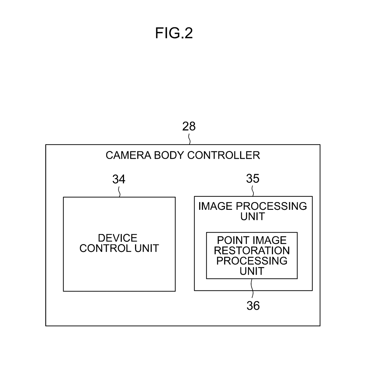
[0202]FIG. 17 is a block diagram illustrating another example of the point image restoration processing unit 36, and illustrates an example of switching a restoration filter according to the presence of a saturation pixel and data of the edge part (image analysis data).

[0203]In this example, the restoration filter is switched on the basis of whether saturation pixel data or pixel data having a pixel value larger than a threshold is included in the edge part (image boundary part) of original image data.

[0204]The image analysis unit 71 includes an edge detection unit 73 that detects the edge part in the image of the original image data, and sends image analysis data showing whether pixel data with a saturated pixel value (saturation pixel data) or pixel data having a pixel value larger than the threshold is included in the...


PUM


Abstract

An image processing device according to an embodiment of the present invention obtains recovery image data by performing restoration processing using a restoration filter based on a point spread function of an optical system, on original image data obtained from an imaging element by imaging using the optical system. The restoration filter used in this restoration processing (a combination filter and realization filter Fr) is generated by combining multiple base filters Fb. Base filter Fb may be arbitrarily selected from filters that are confirmed beforehand to be effective to prevent image quality degradation.

Description

CROSS-REFERENCE TO RELATED APPLICATIONS[0001]This application is a Continuation of PCT International Application No. PCT / JP2013 / 062467 filed on Apr. 26, 2013, which claims priority under 35 U.S.C. §119(a) to Japanese Patent Application No. 2013-027876 filed on Feb. 15, 2013. Each of the above application(s) is hereby expressly incorporated by reference, in its entirety, into the present application.BACKGROUND OF THE INVENTION[0002]Field of the Invention[0003]The present invention relates to an image processing device and an image capture device according to restoration processing based on a point spread function.[0004]Description of the Related Art[0005]In an object image taken by means of an image capture optical system, a so-called point spread phenomenon in which a point object minutely extends may be seen by influences such as diffraction and aberration that originate in the image capture optical system. A function that shows a response to a point light source of an optical syst...

Claims


Application Information

Patent Timeline
Patent Type & Authority Patents(United States)
IPC IPC(8): G06T5/00G06T5/20H04N5/232H04N5/357H04N9/04
CPCG06T5/20H04N5/23229H04N5/357H04N9/045G06T5/003G06T2207/10004H04N23/60H04N23/80H04N25/615H04N25/60H04N23/843H04N25/134
Inventor SUGIMOTO, MASAHIKOHAYASHI, KENKICHINARUSE, YOUSUKE
Owner FUJIFILM CORP
Learn More