Method for operating a non-isolated switching converter having synchronous rectification capability suitable for power factor correction applications

a technology of synchronous rectification and switching converter, which is applied in the direction of dc-dc conversion, power conversion systems, climate sustainability, etc., can solve the problems of discontinuous operation, circuits add cost and complexity to the converter, and the majority of pfc converters cannot absorb this cost, so as to improve efficiency and conversion pfc. , the effect of improving efficiency

Active Publication Date: 2017-04-25
EFFICIENT POWER CONVERSION CORP
View PDF21 Cites 3 Cited by
  • Summary
  • Abstract
  • Description
  • Claims
  • Application Information

AI Technical Summary

Benefits of technology

[0009]According to another embodiment, the first and second switching devices are GaN FET rectifier switches. Techniques are provided for using GaN FETs, or any device with a low reverse recovery charge (Qrr), to realize a synchronous rectifier PFC boost converter operating in the continuous current conduction mode with negative inductor current prevention or insufficient positive inductor current that allows full commutation of the switch to the bus voltage. This technique provides higher efficiency conversion PFC converters by reading input voltage, input current or controller compensation voltage and, if the value is above a pre-determined threshold, providing synchronous rectification to improve efficiency as diode function is then performed by the switch and not the diode. The switch having a much lower on-state voltage than the diode for the same operating conditions therefore yields lower conduction losses than the diode. With precise timing actual “diode” conduction time can be eliminated, thereby increasing efficiency further. The converter can also operate in the non-synchronous mode using the diode for rectification below the predetermined threshold; in this mode, the diode will not conduct as there is insufficient current to complete commutation or the current in the inductor would become negative and would therefore be blocked by the diode.
[0010]GaN offers a simple cost effective solution as it has no reverse-recovery losses when used as a synchronous rectifier. The goal is to achieve synchronous rectification without negative current in the inductor and prevent the rectifier switch from being turned on when there is insufficient energy to complete commutation. This is achieved by operating the boost converter rectifier with a synchronous rectifier (eGaN) operating in the continuous current mode and ensuring that there is sufficient voltage on the input to prevent negative inductor current (and / or currents too small to allow voltage commutation and resulting in diode conduction) and / or forced commutation. If the input voltage is too low, the synchronous rectifier switch is kept in the off state and permitted to operate as a diode. The threshold value of the voltage to switch between synchronous and non-synchronous operation is based on the load current and / or input voltage. The higher the load current, the lower the input voltage may be for synchronous operation. This technique offers a simple and cost effective solution to improve converter efficiency over traditional methods. Furthermore, eGaN FETs allow higher switching frequencies, thereby enabling the reduction of converter size.

Problems solved by technology

Many engineers have tried to design circuits that reduce the impact of reverse-recovery losses on the losses of the converter, but the resulting circuits add cost and complexity to the converter.
Most PFC converters cannot absorb this cost and as such these ideas are not generally adopted.
As a result, operation will become discontinuous near the zero voltage crossing of the AC main source from which power is received due to insufficient voltage to generate sufficient inductor current for self commutation.

Method used


Image

  • Method for operating a non-isolated switching converter having synchronous rectification capability suitable for power factor correction applications
  • Method for operating a non-isolated switching converter having synchronous rectification capability suitable for power factor correction applications
  • Method for operating a non-isolated switching converter having synchronous rectification capability suitable for power factor correction applications

Examples


Embodiment Construction

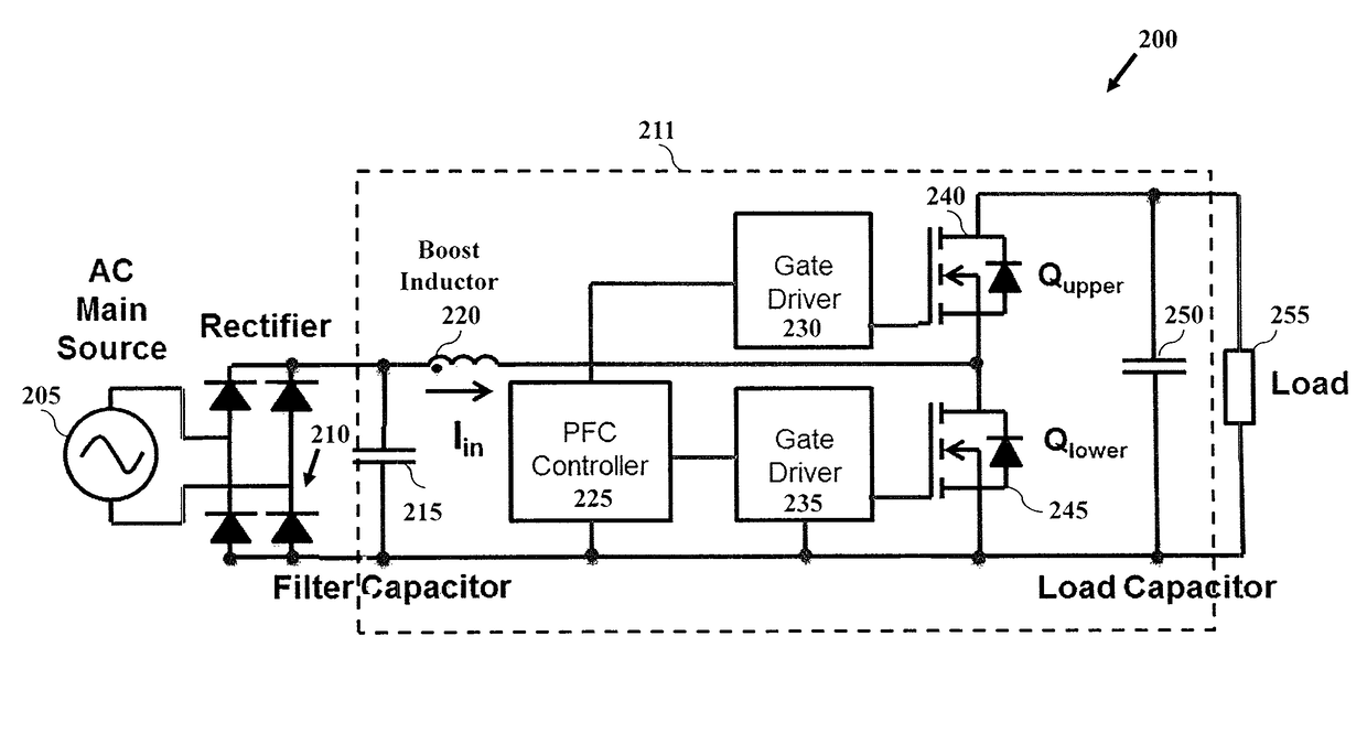
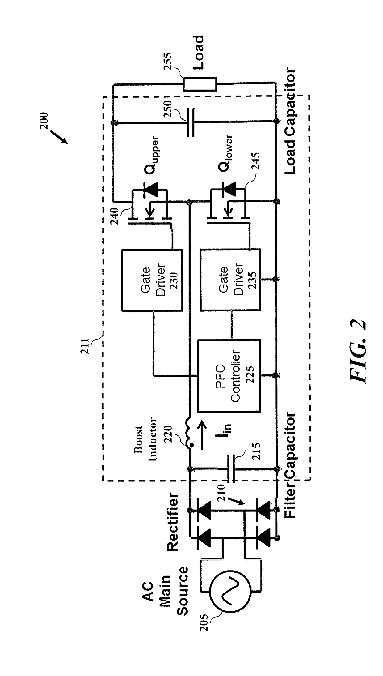
[0020]Referring now to the figures, FIG. 2 depicts a synchronous rectifier boost power factor correction circuit 200 according to one embodiment. The rectifier boost power factor correction circuit 200 includes rectifier circuit 210 and a boost circuit 211. Rectifier boost power factor correction circuit 200 may be coupled to an AC main source 205 to receive voltage and current, and will provide a converted voltage to load 255. The boost circuit 211 includes a filter capacitor 215, an inductor 220, a PFC controller 225, two gate drivers 230, 235, a Qupper switch 240, a Qlower switch 245, a load capacitor 250 and the load 255. In a desired embodiment, the Qupper and Qlower switches are GaN FET rectifier switches.

[0021]The AC main voltage is rectified by the rectifier circuit 210 and filtered by the small filter capacitor 215 to yield a full wave rectified sine-wave voltage, which serves as the source to the boost circuit 211. The inductor current Iin is charged linearly when Qlower s...


PUM


Abstract

A power factor correction (PFC) boost circuit. The PFC boost circuit can include a first switching device, a second switching device, a first gate driver coupled to the first switching device, a second gate driver coupled to the second switching device, and a PFC controller configured to control the first and second gate drivers. The PFC controller will utilize a new technique, referred to herein as “predictive diode emulation” to control the switching devices in a desired manner and to overcome inefficiencies and other problems that might arise using traditional diode emulation. The PFC controller is configured to operate in synchronous and non-synchronous modes.

Description

BACKGROUND OF THE INVENTION[0001]1. Field of the Invention[0002]The present disclosure relates generally to power converters with synchronous rectification, and more particularly to methods and circuits for improving power converter efficiency.[0003]2. Description of the Related Art[0004]Rectifier circuits have many uses, notably as AC-to-DC power converters. Synchronous rectifier configurations aim to improve the power efficiency of power converters and have been widely adopted in low voltage (<40 V) converters.[0005]Power factor correction (PFC) converters traditionally employ a boost converter with current wave shaping based on input voltage following. FIG. 1 depicts a traditional rectifier circuit including a power factor correction circuit. The PFC boost circuit 100 of FIG. 1 includes a PFC controller 125, gate driver 130, switch 135 and diode 140 to provide rectified voltage to a load 150. Other components illustrated in FIG. 1 include an AC main source 105, a mains voltage...

Claims


Application Information

Patent Timeline
Patent Type & Authority Patents(United States)
IPC IPC(8): H02M1/42H02M3/158
CPCH02M1/4208H02M1/4225H02M1/4233H02M3/1588Y02B70/126Y02B70/1466Y02B70/10H02M1/0085
Inventor DE ROOIJ, MICHAEL A.STRYDOM, JOHAN
Owner EFFICIENT POWER CONVERSION CORP
Why Eureka
Try Eureka