Image capturing apparatus and method of controlling image capturing apparatus

a technology of image capturing apparatus and image capturing apparatus, which is applied in the direction of color television details, television system details, television systems, etc., can solve the problems of increasing power consumption during readout, affecting image quality, and deteriorating image quality, so as to achieve the effect of suppressing deterioration in image quality and increasing power consumption

Active Publication Date: 2017-04-25
CANON KK
View PDF3 Cites 0 Cited by
  • Summary
  • Abstract
  • Description
  • Claims
  • Application Information

AI Technical Summary

Benefits of technology

[0007]The present invention has been made in consideration of the above situation, and in an image capturing apparatus, realizes high-speed readout while also suppressing deterioration in image quality without increasing power consumption.

Problems solved by technology

However, in the case in which multiple pixel rows are selected simultaneously and connected, there are cases in which the dynamic range can no longer be ensured.
This issue becomes prominent particularly in cases in which there is a large difference in signals between simultaneously connected pixels.
However, there is an issue of an increase in power consumption during readout due to the raising of the current value for driving the pixels.

Method used


Image

  • Image capturing apparatus and method of controlling image capturing apparatus
  • Image capturing apparatus and method of controlling image capturing apparatus
  • Image capturing apparatus and method of controlling image capturing apparatus

Examples


first embodiment

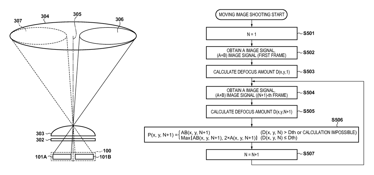
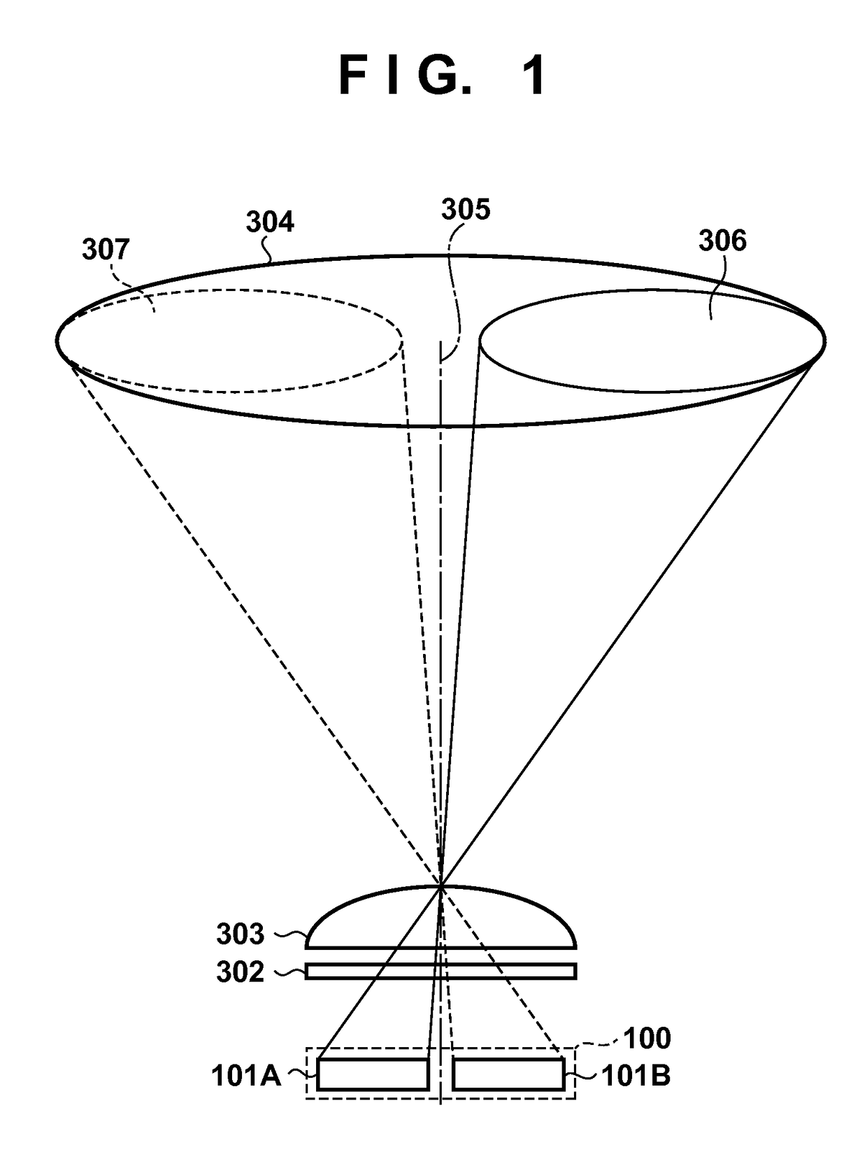
[0021]First, the principles by which a phase difference detection method type of focus detection is realized in a normal image sensor for capturing a subject image will be described. FIG. 1 is a diagram that schematically shows a situation in which luminous flux that has exited from an exit pupil of an imaging lens is incident on one unit pixel of the image sensor. A unit pixel 100 has a first photodiode (PD) 101A and a second photodiode (PD) 101B, and is covered by a color filter 302 and a microlens 303.

[0022]The center of an exit pupil 304 of the imaging lens is an optical axis 305 with regards to a pixel that has the microlens 303. Light that has passed through the exit pupil 304 enters the unit pixels 100 with the optical axis 305 as the center. Also, as shown in FIG. 1, luminous flux that passes through a pupil region 306, which is a portion of the region of the exit pupil 304 of the imaging lens, is received by the first PD 101A through the microlens 303. Similarly, luminous f...

second embodiment

[0045]Next, an image formation method in a second embodiment of the present invention will be described using the flowchart in FIG. 7. A difference from the first embodiment is the point that the operation for replacing the final image signal with a doubled A image signal in step S506 is performed on only G pixels in the second embodiment. Normally, the image sensor 1101 is matched to the human relative luminosity factor, and thus in the case in which the image sensor 1101 is covered with the primary color filter 302, the sensitivity of the G pixel is the highest. For this reason, when obtaining the arithmetic average, only the G pixels where loss of dynamic range is likely to occur are replaced. Note that the same step numbers have been allocated to processes in FIG. 7 that are similar to FIG. 5.

[0046]When an instruction is made to start moving image shooting, the number of frames N is reset to one in step S501. Next, in step S502 the A image signal and the (A+B) image signal in th...

third embodiment

[0050]Next, the third embodiment of the present invention will be described. In the third embodiment, instead of the operation performed in step S506 of the first embodiment in which the final image signal is replaced with a doubled (a multiple of) A image signal, an operation in which the final image signal is replaced with the weighted average of the (A+B) image signal and the A image signal is performed, wherein the weighting is continuously changed between frames.

[0051]FIG. 8 is a table of conditions for calculating the final image signal P(x,y,N+1) in step S506 in the third embodiment. The “frame” column shows the state of the defocus amount in each frame with symbols, and the calculating formulas for the image signal P(x,y,N+1) for the corresponding conditions are listed in the right field.

[0052]For example, in the case in which the condition of the third row is that the defocus amount in two consecutive frames from the (N−1)-th frame is Dth or less, the value of P(x,y,N+1) is...


PUM


Abstract

In an image capturing apparatus having an image sensor including a plurality of unit pixels each having a plurality of photoelectric conversion portions and a microlens, the image sensor can be scanned with a first scan method of adding and reading out signals from a portion of the photoelectric conversion portions by a predetermined number of unit pixels and with a second scan method of adding and reading out signals from the photoelectric conversion portions by the predetermined number of unit pixels. A pixel signal read out with the second scan method is selected if a defocus amount is larger than a threshold value and the larger of the pixel signal read out with the second scan method and a signal obtained by using the pixel signal read out with the first scan method is selected if the defocus amount is equal to the threshold value or less.

Description

BACKGROUND OF THE INVENTION[0001]Field of the Invention[0002]The present invention relates to an image capturing apparatus and a method of controlling an image capturing apparatus.[0003]Description of the Related Art[0004]In recent years, in image capturing apparatuses such as a digital video camera and a digital still camera, imaging with a high number of pixels and at high frame rates due to high-speed readout has become possible following improvements in image sensor sensitivity, enhancements in image processing, and increases in memory capacity. Imaging at a high frame rate has various benefits such as an increase in AF speed and improvements in video quality, and further increases in frame rate are in demand.[0005]On the other hand, a pixel arithmetic averaging method is known as a pixel reduction method for capturing a moving image with a comparatively low number of pixels at a high frame rate using an image capturing apparatus with a high number of pixels. In the pixel arithm...

Claims


Application Information

Patent Timeline
Patent Type & Authority Patents(United States)
IPC IPC(8): H04N5/232H04N5/369H04N5/3745
CPCH04N5/23212H04N5/3696H04N5/37452H04N5/37457H04N25/63H04N23/672H04N25/46H04N25/677H04N25/704H04N25/75H04N25/778H04N25/771
Inventor MASUYAMA, KIMIHIRO
Owner CANON KK
Why Eureka
Try Eureka