Method for forming a plastic support shell of a sole

a technology of plastic support shell and sole, which is applied in the field of sole forming, can solve the problems of low manufacturing accuracy and efficiency, and achieve the effect of easy trimming process, high manufacturing efficiency and easy manufacturing process

Inactive Publication Date: 2017-05-02
YANG TENG JEN
View PDF2 Cites 0 Cited by
  • Summary
  • Abstract
  • Description
  • Claims
  • Application Information

AI Technical Summary

Benefits of technology

[0007]The primary objective of the present invention is to provide a method for forming a plastic support shell of a sole which is capable of overcoming the low manufacturing accuracy and efficiency of the conventional method.
[0016]It is to be noted that the hole alignment portions of the mold insert allows the plastic semi product to be formed with the cutting edge, the cutting insert is formed in the shape of the chamber of the plastic semi product, and the edge of the cutting cavity is only able to come into contact with the cutting edge of the plastic semi product. With all these arrangements, holes can be directly formed and the waste edge can be directly cut off when the cutting mold assembly is closed, which makes the manufacturing process very easy. Furthermore, the plastic semi product is a thin shell structure, so that the follow-up steps cannot be performed if the plastic semi product is not held tight. The present invention uses the carrying mold and the pressing mold to press against the inner and outer surfaces of the plastic semi product, and uses the restricting edge and the support edge to define the cutting line. Therefore, the plastic semi product can be firmly positioned and held tight, and then the mechanical arm can trim the plastic semi product under the guiding of the restricting edge and the support edge, which makes the trimming process easy and precise.

Problems solved by technology

Since the semi product is a thin shell, it will be difficult to fix the thin shell semi product during the cutting, trimming and drilling process, which will result in low manufacturing accuracy and efficiency.

Method used


Image

  • Method for forming a plastic support shell of a sole
  • Method for forming a plastic support shell of a sole
  • Method for forming a plastic support shell of a sole

Examples


Embodiment Construction

[0030]The present invention will be clearer from the following description when viewed together with the accompanying drawings, which show, for purpose of illustrations only, the preferred embodiment in accordance with the present invention.

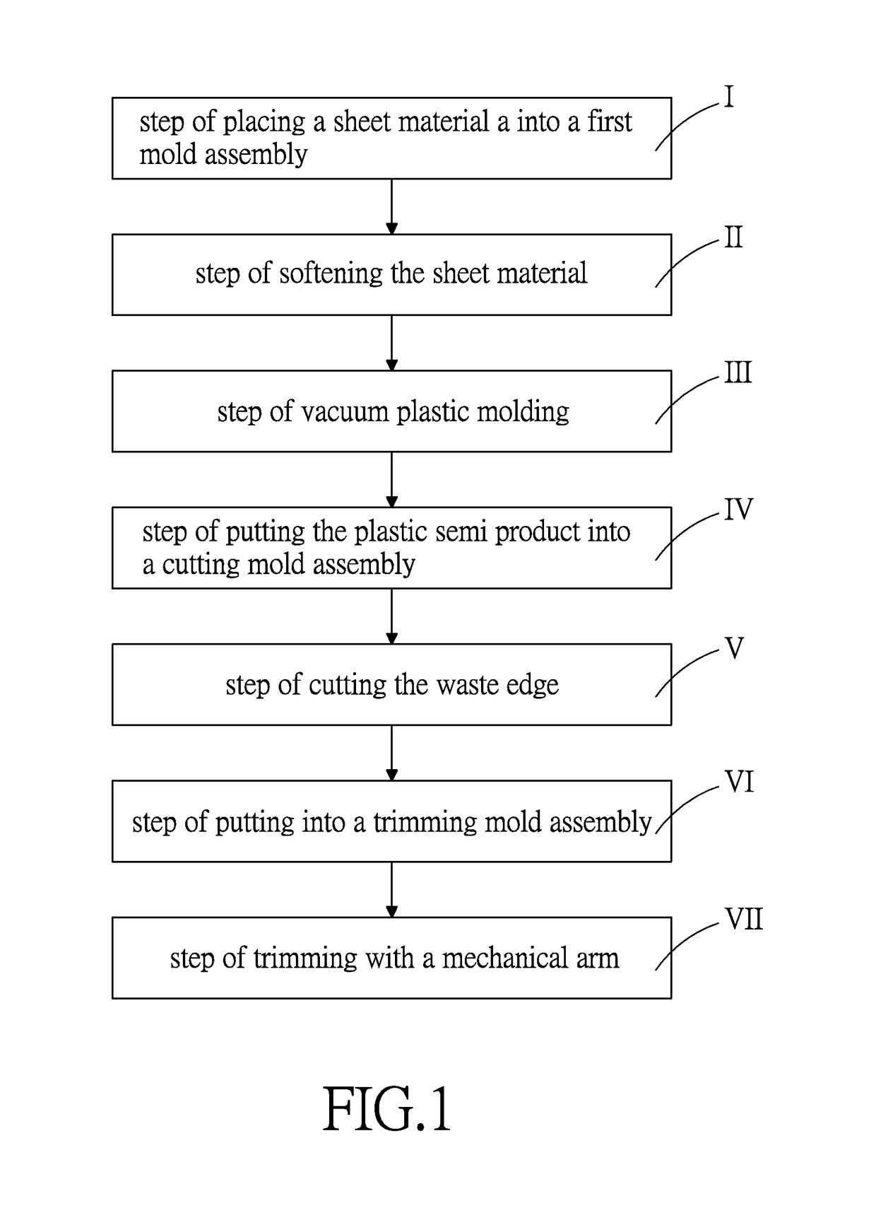
[0031]Referring to FIGS. 1-13, a method for forming a plastic support shell of a sole in accordance with present invention comprises the following steps:

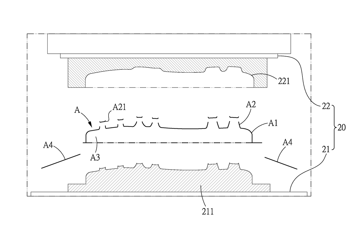
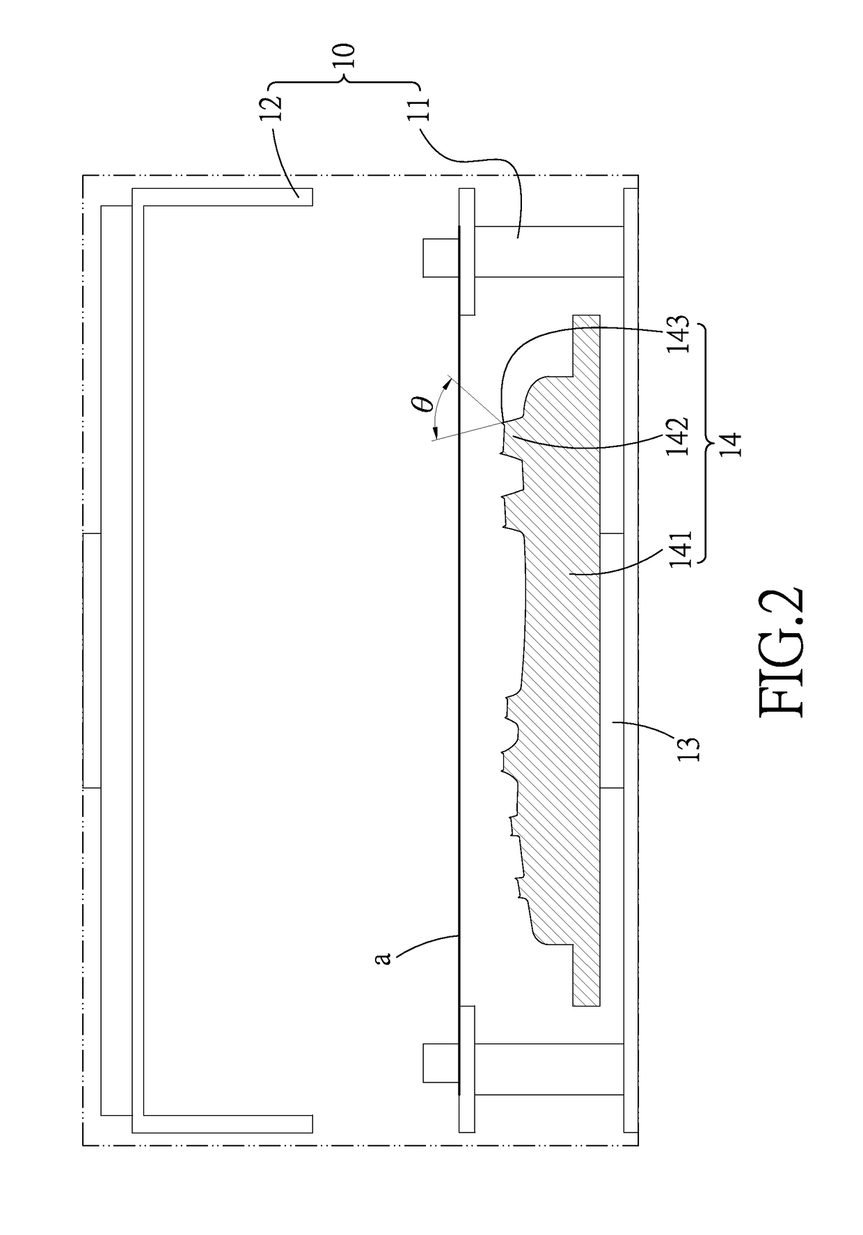
[0032]A step I of placing a sheet material a into a first mold assembly 10, the first mold assembly 10 includes a first mold 11 and an opposite second mold 12. The first mold 11 includes an extendable and retractable seat 13 which is movable with respect to the second mold 12. On the extendable and retractable seat 13 is provided a mold insert 14 which includes a molding portion 141 and a plurality of hole alignment portions 142 formed on the molding portion 141. Each of the hole alignment portions 142 includes a cutting edge 143 which has a cutting angle θ less than 45 degrees. The sheet materia...


PUM

PropertyMeasurementUnit
cutting angleaaaaaaaaaa
dimensionaaaaaaaaaa
shapeaaaaaaaaaa

Abstract

A method for forming a plastic support shell of a sole includes the steps of placing a sheet material into a first mold assembly; softening the sheet material; vacuum plastic molding; putting the plastic semi product into a cutting mold assembly; cutting the waste edge; putting into a trimming mold assembly; and trimming with a mechanical arm. The carrying mold and the pressing mold press against the inner and outer surfaces of the plastic semi product, and the restricting edge and the support edge are used to define a cutting line. Therefore, the plastic semi product can be firmly positioned and held tight, and then the mechanical arm can trim the plastic semi product under the guiding of the restricting edge and the support edge, which makes the trimming process easy and precise.

Description

BACKGROUND OF THE INVENTION[0001]Field of the Invention[0002]The present invention relates to a method for forming a sole, and more particularly to a method for forming a plastic support shell of a sole.[0003]Description of the Prior Art[0004]Foamed plastic can find wide application in the production of commodities of daily use, in transportation, industrial manufacturing and even in aero mechanical industry.[0005]The manufacturing process varies depending on what purpose the foamed plastic is used for. For example, when it is used as an insole of a shoe, the foamed plastic must be formed to fit the shape of the sole, and the conventional method for forming this kind of foamed plastic not only involves the step of forming a semi product in the form of a thin shell by vacuum plastic molding, but also involves the steps of taking out the semi product, cutting, trimming and drilling. Since the semi product is a thin shell, it will be difficult to fix the thin shell semi product during ...

Claims


Application Information

Patent Timeline
Patent Type & Authority Patents(United States)
IPC IPC(8): B29C43/02B29D35/12B29C51/10B29L31/50
CPCB29D35/122B29C51/10B29C2793/009B29C2793/0018B29C2793/0027B29L2031/504B29C51/32A43D8/36A43D27/00B29D35/128A43D87/00B29C49/42826
Inventor YANG, TENG-JEN
Owner YANG TENG JEN
Why Eureka
Try Eureka