

Method of and system for evacuating fluid in a sea vessel
a technology for evacuating fluid and sea vessels, applied in vessel construction, positive displacement liquid engines, instruments, etc., can solve the problems of bilge pump to spin in air, loss of head pressure in the bilge pump hose,
- Summary
- Abstract
- Description
- Claims
- Application Information
AI Technical Summary
Benefits of technology
Problems solved by technology
Method used
Image

Examples
Embodiment Construction
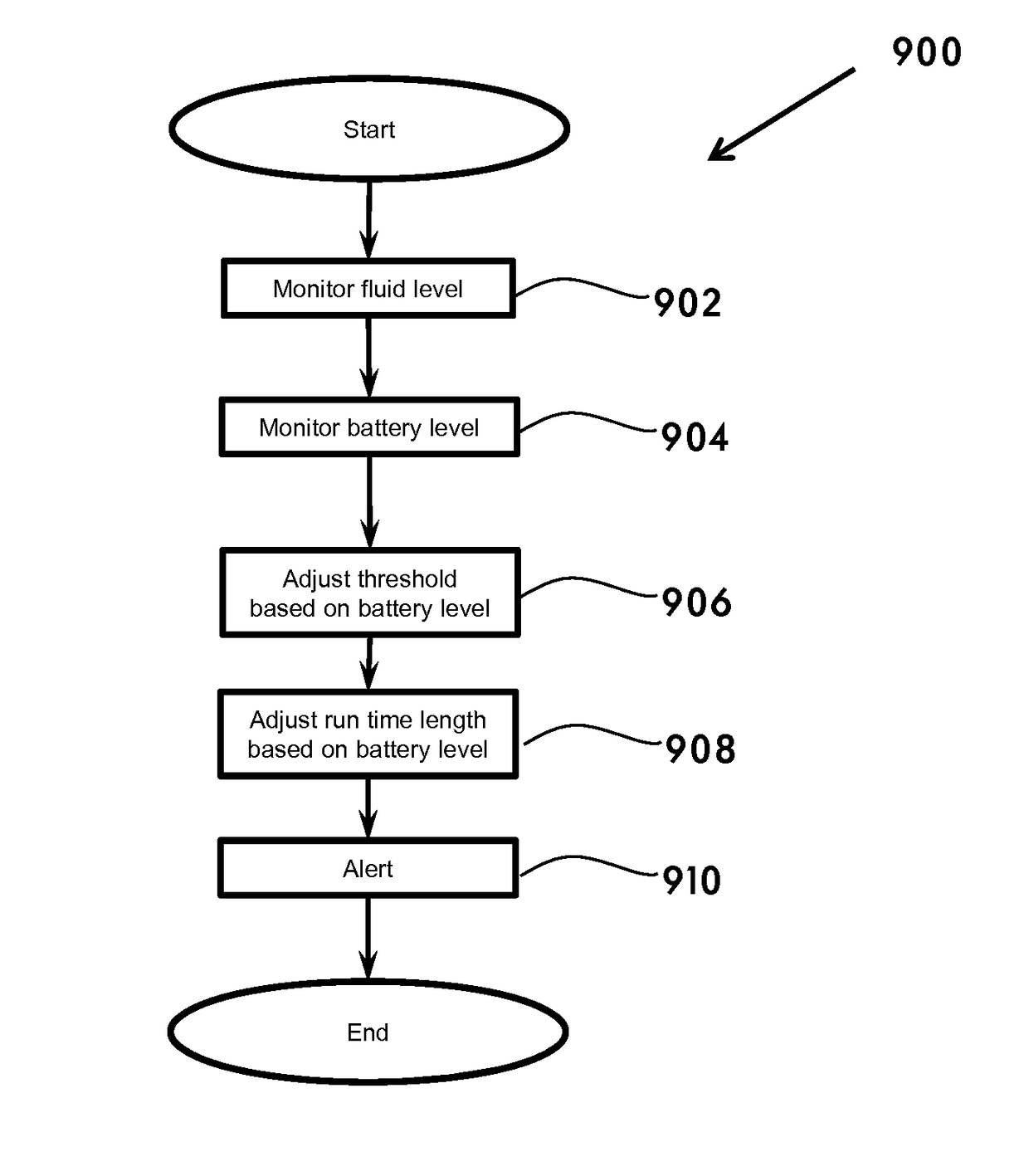
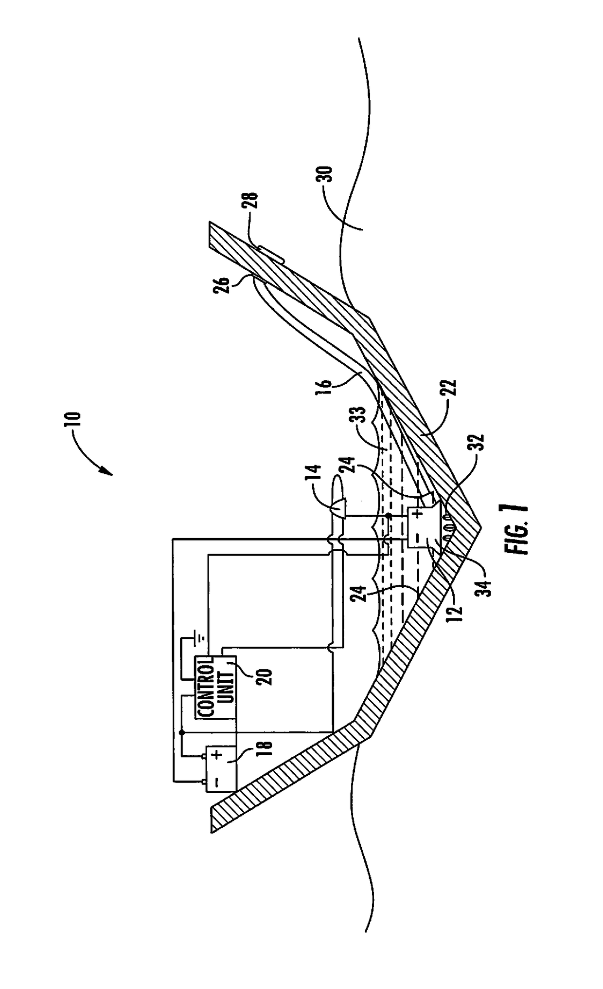
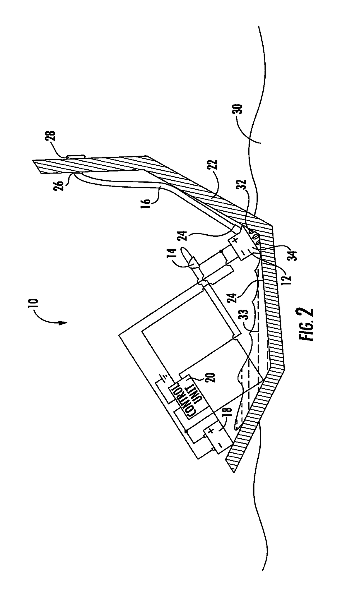
[0059]The present invention advantageously provides a system and method for evacuating fluid in a sea vessel, including any boat, ship, tank, or the like. More particularly, the invention provides a system and method that is adaptable to any size vessel or bilge pump based on a learned experience gained by sensory information over one or more bursts of time, whereby sensory information may include without limitation current draw, frequency switch toggling information, battery consumption fluctuation information, and voltage consumption information. The present invention contemplates that different types of sea vessels have different types of bilge systems and pumps. Therefore each system has unique run time requirements in order to minimize power consumption over time.
[0060]Accordingly, the components of the system have been represented where appropriate by conventional symbols in the drawings, showing only those specific details that are pertinent to understanding the embodiments o...
PUM
 Abstract
Description
Claims
Application Information