

Method and tool for producing a surface of predetermined roughness
a surface and predetermined technology, applied in the direction of turning machine accessories, honing tools, cutting inserts, etc., can solve the problems of insufficient roughness of the substrate surface, inability to mass production, and inability to introduce constant quality and shaping structures into the substrate, etc., to achieve excellent and permanent adhesion of the layer, reduce the cutting force at the individual teeth, and reduce the effect of tool life travel
- Summary
- Abstract
- Description
- Claims
- Application Information
AI Technical Summary
Benefits of technology
Problems solved by technology
Method used
Image

Examples
Embodiment Construction
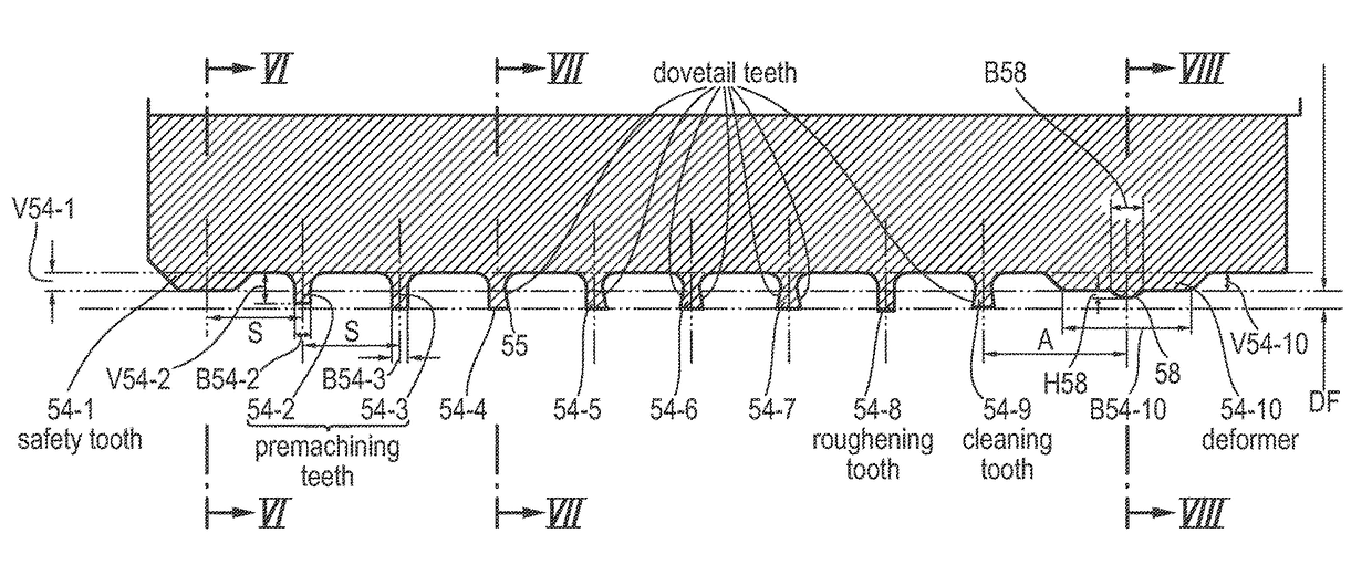
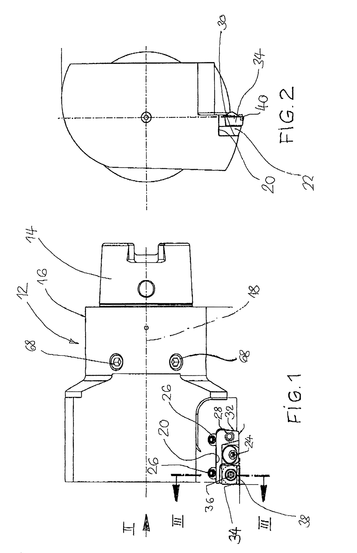
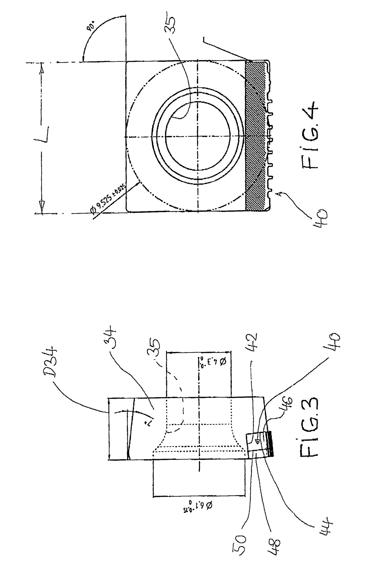
[0044]In the following a tool will be described with which a cylindrical inner surface of a substrate, in particular a bore of an engine block that has been prepared to size or premachined can be worked in such a way that a layer can be applied by a thermal spraying method in mass production. By means of this material application by so-called thermal spraying a liner, for example, of steel with traces of other elements, is to be produced, in particular in the form of a matrix with embedded oxide nests and very fine pores. The finished thickness of this layer should then be approximately 0.1 to 0.2 mm wherein after honing this layer exhibits a very smooth surface with very fine pores.
[0045]In order for the material applied by thermal spraying to adhere well on the substrate, i.e., a cast aluminum material, it is required to provide the substrate with a special surface so that interlocking between the material layer applied by thermal spraying and the cast aluminum can be realized acr...
PUM
| Property | Measurement | Unit |
|---|---|---|
| width | aaaaa | aaaaa |
| depth | aaaaa | aaaaa |
| depth | aaaaa | aaaaa |
Abstract
Description
Claims
Application Information