Transflective liquid crystal display panel and a liquid crystal display device

a liquid crystal display panel and transparent technology, applied in non-linear optics, instruments, optics, etc., can solve the problems of image not being able to be displayed in the dark, low reflectivity of light emitted, high energy consumption, etc., to improve the display quality of the liquid crystal display device and simplify the manufacturing process.

Active Publication Date: 2017-05-09
TCL CHINA STAR OPTOELECTRONICS TECH CO LTD
View PDF1 Cites 0 Cited by
  • Summary
  • Abstract
  • Description
  • Claims
  • Application Information

AI Technical Summary

Benefits of technology

[0008]In order to solve the problem existing in the current technology of the transflective liquid crystal panel, one embodiment of the disclosure provides a transflective liquid crystal panel and a liquid crystal display device comprising the transflective liquid crystal panel. Under the guarantee for the equivalence for the cell gap of the liquid crystal cell in the transmissive region and the reflective region, the manufacturing process of the liquid crystal panel can be simplified. The chromatic aberration between the transmissive region and the reflective region decreases and the color congruity is ensured. The displaying quality of the liquid crystal display device is increased.
[0019]The embodiment of the disclosure provides a transflective liquid crystal panel having pixel electrodes in a bent-stripped form with different bending angles in the transmissive region and the reflective region. The bending angle of the pixel electrode in the transmissive region is smaller than the bending angle of the pixel electrode in the reflective region such that the phase delays of the liquid crystal in the transmissive region and the reflective region matches with each other. Therefore the cell gap of the liquid crystal cell does not need change. The consistency of the cell gap of the liquid crystal cell greatly simplifies the manufacture process for the liquid display panel, and improves the display quality of the liquid crystal display device.

Problems solved by technology

However the drawback is the transmissive light is a small portion of the light emitted from the backlight.
In order to improve the display luminance it needs to greatly improve the brightness of the backlight, and therefore the energy consumption is high.
However the drawback is that the image cannot be displayed in the dark due to the dependence on the external light source.
However, the drawback of the transflective type LCD panel is that the light from the transmissive region only passes through the liquid crystal layer once, and the light from the reflective region passes through the liquid crystal layer twice.
This results in the color incongruity for the image displayed in the transflective type LCD device.
However, the cell gap existing among the liquid crystal cells of the transflective liquid crystal panel complicates the manufacture process, and makes it difficult to control the uniformity of the cell gap.

Method used


Image

  • Transflective liquid crystal display panel and a liquid crystal display device
  • Transflective liquid crystal display panel and a liquid crystal display device
  • Transflective liquid crystal display panel and a liquid crystal display device

Examples


Embodiment Construction

[0026]The following description with reference to the accompanying drawings is provided to explain the transflective liquid crystal panel and the liquid crystal display for those skilled in the art to better understand the exemplary embodiments of the disclosure.

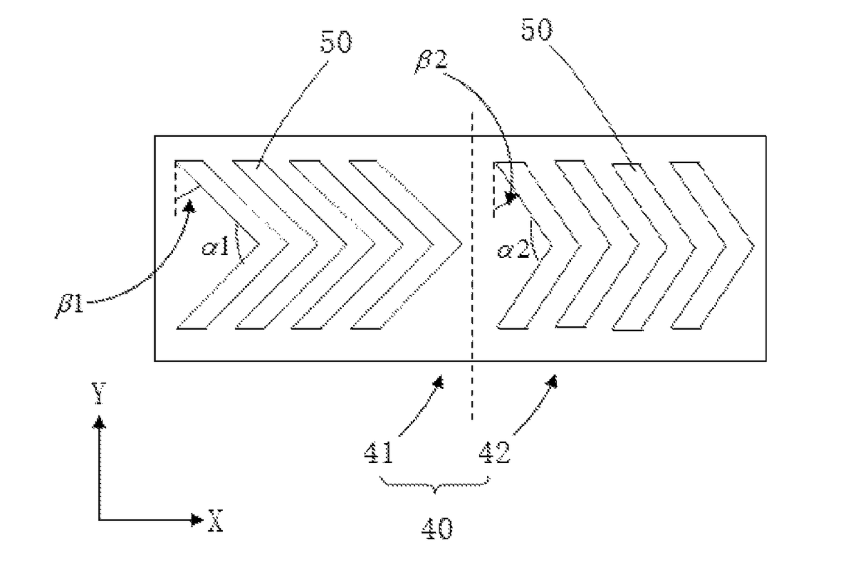
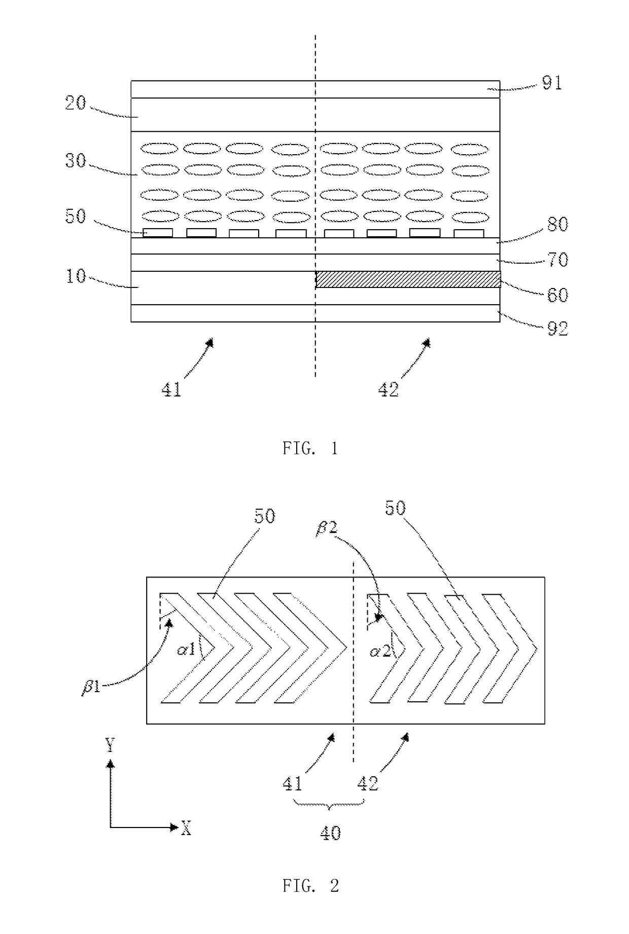
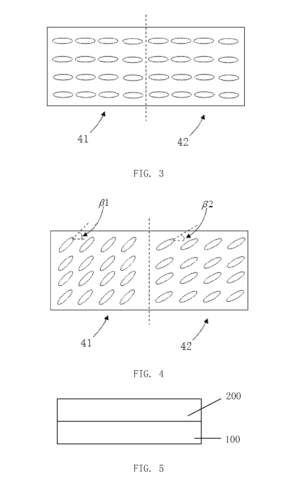
[0027]Refer to FIG. 2 and FIG. 3. The transflective liquid crystal panel of the embodiment comprises an array substrate 10, a color filter substrate 20 and a liquid crystal layer 30 disposed between the array substrate 10 and the color filter substrate 20. The array substrate 10 comprises a plurality of pixel regions 40. Each of the pixel region 40 comprises a transmissive region 41 and a reflective region 42. The array substrate 10 further comprises a plurality of pixel electrodes 50 disposed in the pixel region 40. Each of the pixel electrode 50 is in a bent-stripped form and spaced from each other. Furthermore, the bending angle of the pixel electrode in the transmissive region 41 is α1, and the bending angle of the pixel...


PUM

PropertyMeasurementUnit
bending angleaaaaaaaaaa
phase delayaaaaaaaaaa
optical path differenceaaaaaaaaaa

Abstract

The disclosure is related to a transflective liquid crystal panel comprising a array substrate, a color filter substrate opposite to the array substrate and a liquid crystal layer disposed between the array substrate and the color filter substrate. The array substrate comprises a plurality of pixel regions, each of which comprising a reflective region, a transmissive region and a plurality of pixel electrodes in a bent-stripped form and spaced from each other. The bending angle of the pixel electrode in the transmissive region is , and the bending angle of the pixel electrode in the reflective region is , wherein so that the amount of phase delay in the transmissive region matches with the amount of phase delay in the reflective region. The disclosure is also related to a liquid crystal display device comprising the transflective liquid crystal panel.

Description

BACKGROUND[0001]Technical Field[0002]The disclosure is related to liquid crystal display technology field, and more particular to a transflective liquid crystal panel and a liquid crystal display device having the transflective liquid crystal panel.[0003]Related Art[0004]Liquid crystal displays (abbreviated as LCD) with its excellent performance and mature technology currently have become mainstream products on the market. Liquid crystal panels are the key components of liquid crystal displays. Liquid crystal panels are mainly formed by color filter substrates and array substrates through cell assembly. The liquid crystal is filled between the color filter substrate and the array substrate to form a liquid crystal cell. Types of LCD panels can be divided as transmissive type, reflective type and transflective type according to the type of the light source.[0005]The transmissive type LCD panel adopts a backlight as the light source. The backlight is disposed on the rear side of the l...

Claims


Application Information

Patent Timeline
Patent Type & Authority Patents(United States)
IPC IPC(8): G02F1/1335G02F1/1333G02F1/1343
CPCG02F1/133555G02F1/1333G02F1/1343G02F1/13439G02F1/133514G02F1/133528G02F1/134309G02F2001/133531G02F2201/121G02F2201/123G02F2203/01G02F1/133345G02F1/133553G02F1/134327G02F1/134363G02F1/134372G02F1/133531
Inventor XIE, CHANG
Owner TCL CHINA STAR OPTOELECTRONICS TECH CO LTD
Why Eureka
Try Eureka