Image processing apparatus, image capturing apparatus, and display apparatus

a technology of image processing and display apparatus, which is applied in the direction of image enhancement, color signal processing circuit, instruments, etc., can solve the problems of reducing accuracy and resolution in long-distance view. , to achieve the effect of improving depth

Active Publication Date: 2017-05-09
SHARP KK
View PDF12 Cites 0 Cited by
  • Summary
  • Abstract
  • Description
  • Claims
  • Application Information

AI Technical Summary

Benefits of technology

[0022]According to the present invention, it is possible to generate an image having an improved sense of depth also in long-distance view to resolve the first problem described above.
[0023]According to the present invention, it is possible to cause a user to feel the sense of depth to resolve the second problem described above.
[0024]According to the present invention, it is possible to generate an image for which the user feels depth to resolve the third problem described above.

Problems solved by technology

However, the method disclosed in PTL 1 has a first problem in that, since accuracy and resolution in long-distance view are reduced when the depth data is acquired using the active method or the passive method, the adjustment in the long-distance view in accordance with the depth is disabled not to possibly provide the sense of depth.
However, PTL 1 has a second problem in that, when the depth data is acquired using the active method or the passive method, the accuracy and the resolution in the long-distance view are reduced.
In other words, the resolution of the depth is lost in the long-distance view in which the reflected light of the infrared light cannot be detected to disable accurate representation of the depth.
As a result, the image processing apparatus in the related art is not capable of performing the image processing corresponding to the depth in such long-distance view to cause a user not to sufficiently feel the depth.
The image processing apparatus in PTL 1 has a third problem in that, since the image processing apparatus in PTL 1 is not capable of setting appropriate image processing parameters in these cases, it is not possible to adjust the sense of depth for the image to cause the user not to feel the depth.

Method used


Image

  • Image processing apparatus, image capturing apparatus, and display apparatus
  • Image processing apparatus, image capturing apparatus, and display apparatus
  • Image processing apparatus, image capturing apparatus, and display apparatus

Examples


first embodiment

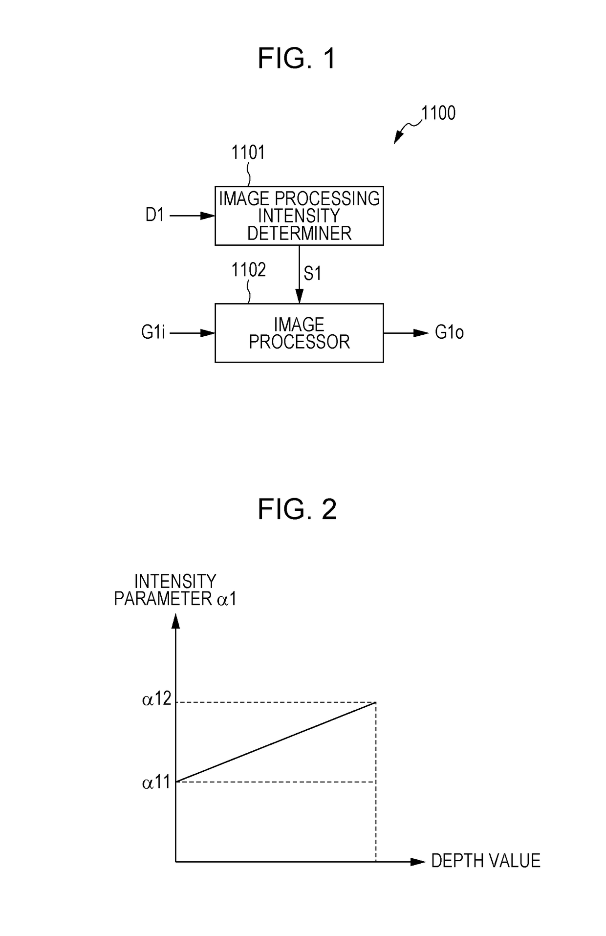
[0059]FIG. 1 is a block diagram schematically illustrating the configuration of an image processing apparatus 1100 in a first embodiment of the present invention. Image information G1i, which is an input image, and depth information D1 corresponding to the image information G1i are input into the image processing apparatus 1100. The image processing apparatus 1100 performs image processing to the image information G1i on the basis of the depth information D1 to output the result of the processing as output image information G1o. The image information G1i may be data or a signal representing a moving image, such as a video signal, or may be data or a signal representing a still image, such as a Joint Photographic Experts Group (JPEG) file.

[0060]The depth information D1 corresponding to the image information G1i is information representing a depth value at each pixel in the image information G1i. The depth value at a pixel is a value representing the distance from a point of view to a...

second embodiment

[0084]FIG. 6 is a block diagram schematically illustrating the configuration of an image capturing apparatus 1300 in a second embodiment of the present invention. The image capturing apparatus 1300 includes an imaging device 1200, an imaging device 1201, an image processing unit 1100a, an image display unit 1203, and an image storage unit 1204. The image processing unit 1100a includes a parallax calculator 1202, the image processing intensity determiner 1101, and the image processor 1102. The same reference numerals (1101 and 1102) are used in FIG. 6 to identify the same components illustrated in FIG. 1. A description of such components is omitted herein.

[0085]The imaging devices 1200 and 1201 are each composed of a lens module and a charge coupled device (CCD) imager or a complementary metal oxide semiconductor (CMOS) imager. The imaging device 1200 is arranged in parallel with the imaging device 1201. In other words, the point of view of an image captured and generated by the imag...

third embodiment

[0092]FIG. 8 is a block diagram schematically illustrating the configuration of an image display apparatus 1301 in a third embodiment of the present invention. The image display apparatus 1301 includes an image processing unit 1100b and the image display unit 1203. The image processing unit 1100b includes the depth information calculator 1205, the image processing intensity determiner 1101, and the image processor 1102. The same reference numerals (1101, 1102, and 1203) are used in FIG. 8 to identify the same components illustrated in FIG. 6. A description of such components is omitted herein.

[0093]The depth information calculator 1205 estimates the depth value corresponding to each pixel in the image information G1i that is input on the basis of the image information G1i to supply the depth information including the result of the estimation to the image processing intensity determiner 1101. Various estimation methods in the related art can be used for the estimation of the depth va...


PUM


Abstract

An image processing apparatus includes an image processing intensity determination unit that determines an intensity of image processing and an image processing unit that performs the image processing to image information in accordance with the intensity determined by the image processing intensity determination unit. The image processing intensity determination unit determines the intensity of the image processing at a target pixel included in the image information on the basis of a depth value indicating a depth corresponding to the target pixel and a vertical position of the target pixel in the image information.

Description

TECHNICAL FIELD[0001]The present invention relates to an image processing apparatus, an image capturing apparatus, and a display apparatus.[0002]This application is based upon and claims the benefit of priority of the prior Japanese Patent Application No. 2011-277591 filed on Dec. 19, 2011, Japanese Patent Application No. 2011-281945 filed on Dec. 22, 2011, and Japanese Patent Application No. 2011-282026 filed on Dec. 22, 2011, the entire contents of which are incorporated herein by reference.BACKGROUND ART[0003]The following matters are known as first background art. In taking a still image or a movie with a camera or displaying the still image or the movie on a monitor, various image processing technologies have been developed in order to improve sharpness and clarity. For example, a contour enhancement process to improve the sharpness and a color saturation enhancement process to improve the clarity are exemplified as the image processing in related art. In addition, the image pr...

Claims


Application Information

Patent Timeline
Patent Type & Authority Patents(United States)
IPC IPC(8): H04N13/02H04N13/00G06T7/00H04N9/68H04N5/208H04N13/128
CPCG06T7/586H04N5/208H04N9/68H04N13/0018G06T2207/10012G06T2207/20192H04N13/0239H04N2013/0081H04N13/122H04N13/239H04N13/128
Inventor TOKUI, KEIMIZUSHIMA, SHIGEAKI
Owner SHARP KK
Why Eureka
Try Eureka