
Wire harness with metal pipe and cap

a wire harness and metal pipe technology, applied in the direction of insulated conductors, cables, electric/fluid circuits, etc., can solve the problems of difficult to ensure the engagement space of the coating-protective cap, hurting the coating of the electric wire, etc., and achieve the effect of hard to cause damag

Active Publication Date: 2017-05-16
YAZAKI CORP
View PDF25 Cites 0 Cited by
  • Summary
  • Abstract
  • Description
  • Claims
  • Application Information

AI Technical Summary

Benefits of technology

This configuration enables the engagement of a coating-protective cap without upsizing the metal pipe, preventing damage to the wire coatings and allowing for easier installation under vehicle floors while maintaining a small pipe diameter, thus reducing the risk of injury and improving compatibility with various wire configurations.

Problems solved by technology

Because the coatings of the electric wires might be hurt when this edge portion contacts with the coatings, it is considered to be necessary to engage a coating-protective cap with the terminal opening of the metal pipe.
Therefore, because the gap between the electric wires and the inner surface of the metal pipe is small, there is the following problem.
That is, it is difficult to ensure a space where the coating-protective cap is engaged.

Method used


Image

  • Wire harness with metal pipe and cap
  • Wire harness with metal pipe and cap
  • Wire harness with metal pipe and cap

Examples


embodiment

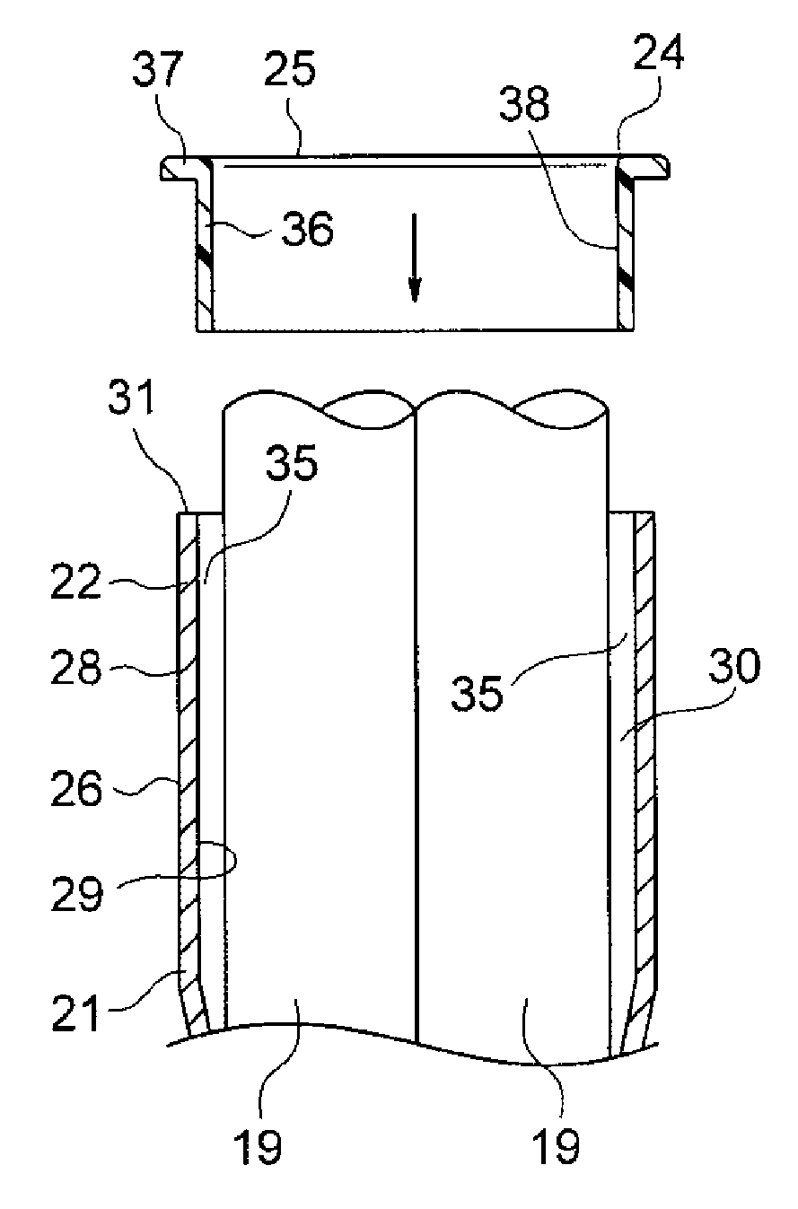
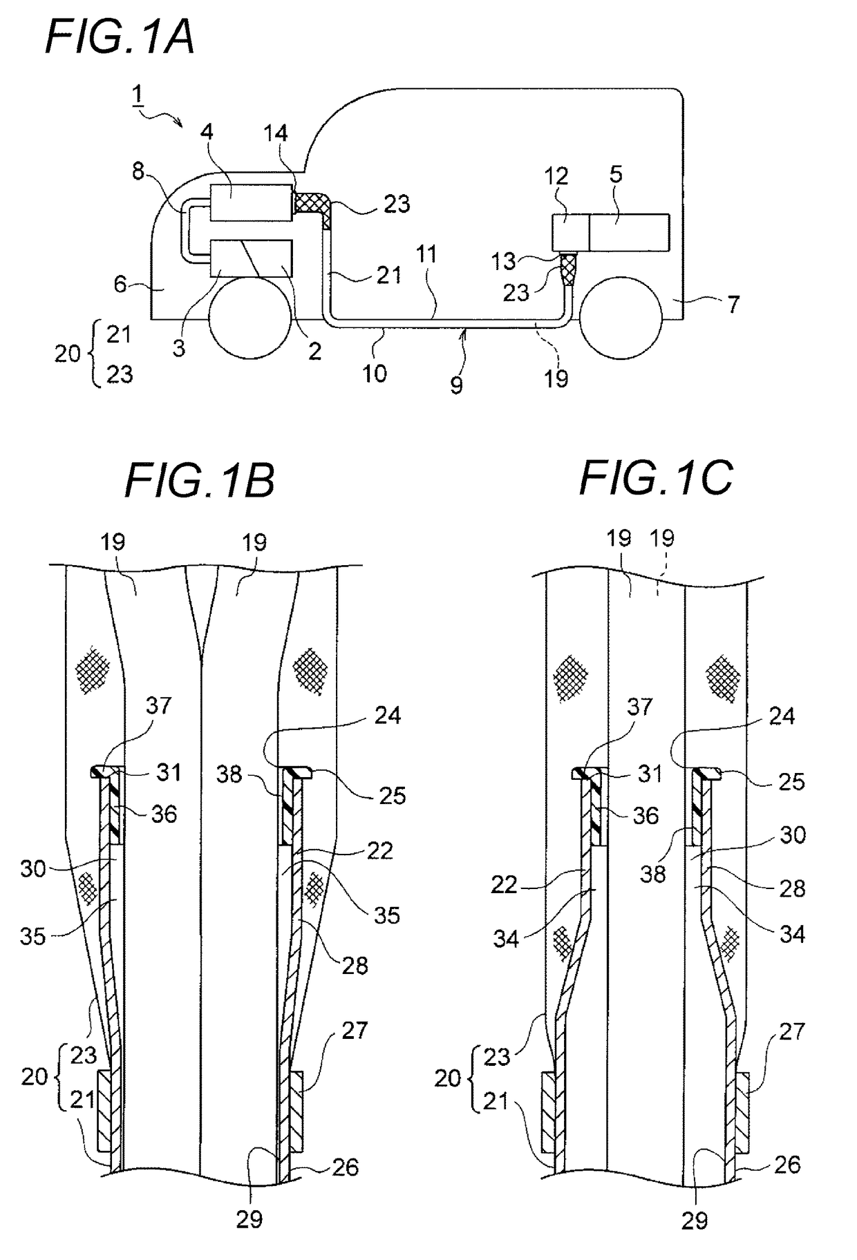
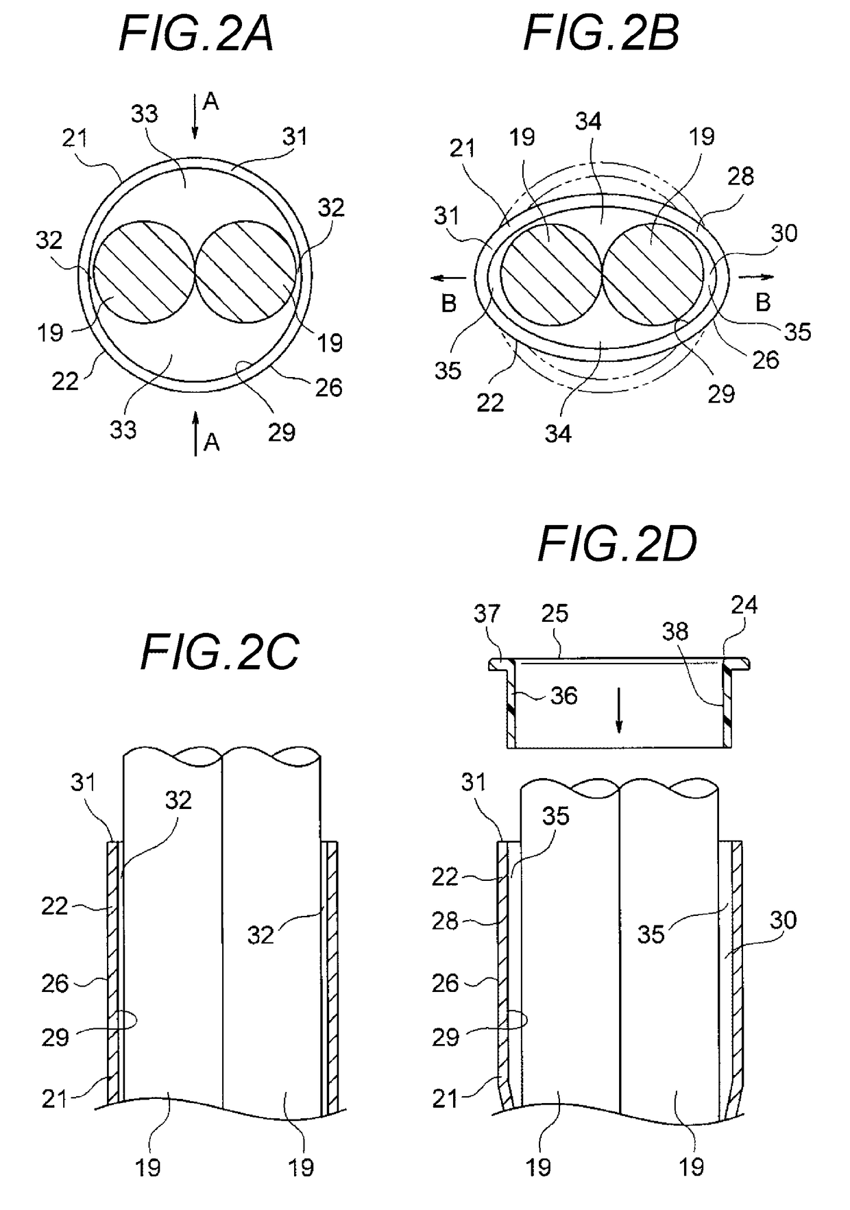
[0027]Hereinafter, an embodiment of the present invention is described with reference to the drawings. FIG. 1A is a schematic view of a vehicle in which a wire harness according to an embodiment of the present invention is wired. FIGS. 1B and 1C are sectional views of a metal pipe terminal part of the wire harness. FIGS. 2A to 2D show a processing of the metal pipe terminal part, in which FIG. 2A is an end view before being crushed, FIG. 2B is an end view after being crushed, FIG. 2C is a horizontal sectional view of FIG. 2A, and FIG. 2D is a horizontal sectional view of FIG. 2B and a sectional view of a coating-protective cap. FIG. 3A is a sectional view in a processing of a metal pipe terminal part according to another example when there are three high voltage electric wires. FIG. 3B is a sectional view in a processing of a metal pipe terminal part according to another example when there are four high voltage electric wires.

[0028]In the description, an example in which a wire harn...


PUM

PropertyMeasurementUnit
shapeaaaaaaaaaa
diameteraaaaaaaaaa
thicknessaaaaaaaaaa

Abstract

A wire harness includes conducting paths, a metal pipe into which the conducting paths are inserted, and a conducting path protective cap which includes a through hole for the conducting paths, and an engaging part which is engaged with a terminal part of the metal pipe. The terminal part of the metal pipe has a ring-like cap engagement space formed by crushing the terminal part towards a predetermined direction from a pipe outer surface of the metal pipe. The ring-like cap engagement space includes a reduced space and an enlarged space formed due to a crushing of the terminal part. The reduced part is formed by narrowing a part of a gap between the conducting paths and the pipe inner surface due to the crushing, and the enlarged space is formed by enlarging a part of the gap in accordance with a formation of the reduced space.

Description

CROSS REFERENCE TO RELATED APPLICATIONS[0001]This application is a continuation of PCT application No. PCT / JP2012 / 081725, which was filed on Nov. 30, 2012 based on Japanese Patent Application (No. 2011-261644) filed on Nov. 30, 2011, the contents of which are incorporated herein by reference.BACKGROUND OF THE INVENTION[0002]1. Field of the Invention[0003]The present invention relates to a wire harness including a plurality of conducting paths, a metal pipe and a cap.[0004]2. Description of the Related Art[0005]A high voltage wire harness is used to electrically connect devices of a hybrid vehicle or an electric vehicle, namely, devices such as a motor unit, an inverter unit or a battery in the vehicle.[0006]A wire harness disclosed in JP-A-2004-171952 includes three electric wires which are electrically connected between devices, and a metal pipe which accommodates and shields the three electric wires for most of the full length.[0007]The metal pipe has conductivity to have a shield...

Claims


Application Information

Patent Timeline
Patent Type & Authority Patents(United States)
IPC IPC(8): H01B7/00B60R16/02H02G3/04
CPCB60R16/0215H02G3/0481
Inventor OGA, TATSUYAYOSHIDA, HIROYUKI
Owner YAZAKI CORP
Learn More