Supercharge Your Innovation With Domain-Expert AI Agents!

Electronic combined load weak link

Active Publication Date: 2017-05-16
DEN NORSKE STATS OLJESELSKAP AS
View PDF23 Cites 3 Cited by
  • Summary
  • Abstract
  • Description
  • Claims
  • Application Information

AI Technical Summary

Benefits of technology

The invention aims to provide a device and method that can safely and predictably disconnect risers in various applications without causing damage to the well barrier. This device can increase the operating envelope of the riser and can be used in drilling risers, well intervention risers, completion / work over risers, flexible production risers, offloading hoses, and other riser applications.

Problems solved by technology

In such accidental scenarios operators will have very limited time to recognize that an accident is happening and to trigger a release of the riser from the well or other critical structure(s) attached to the riser.
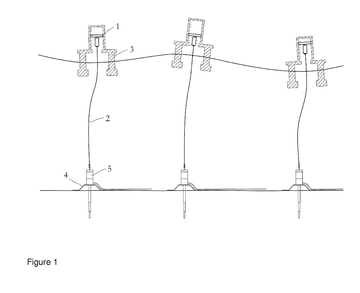
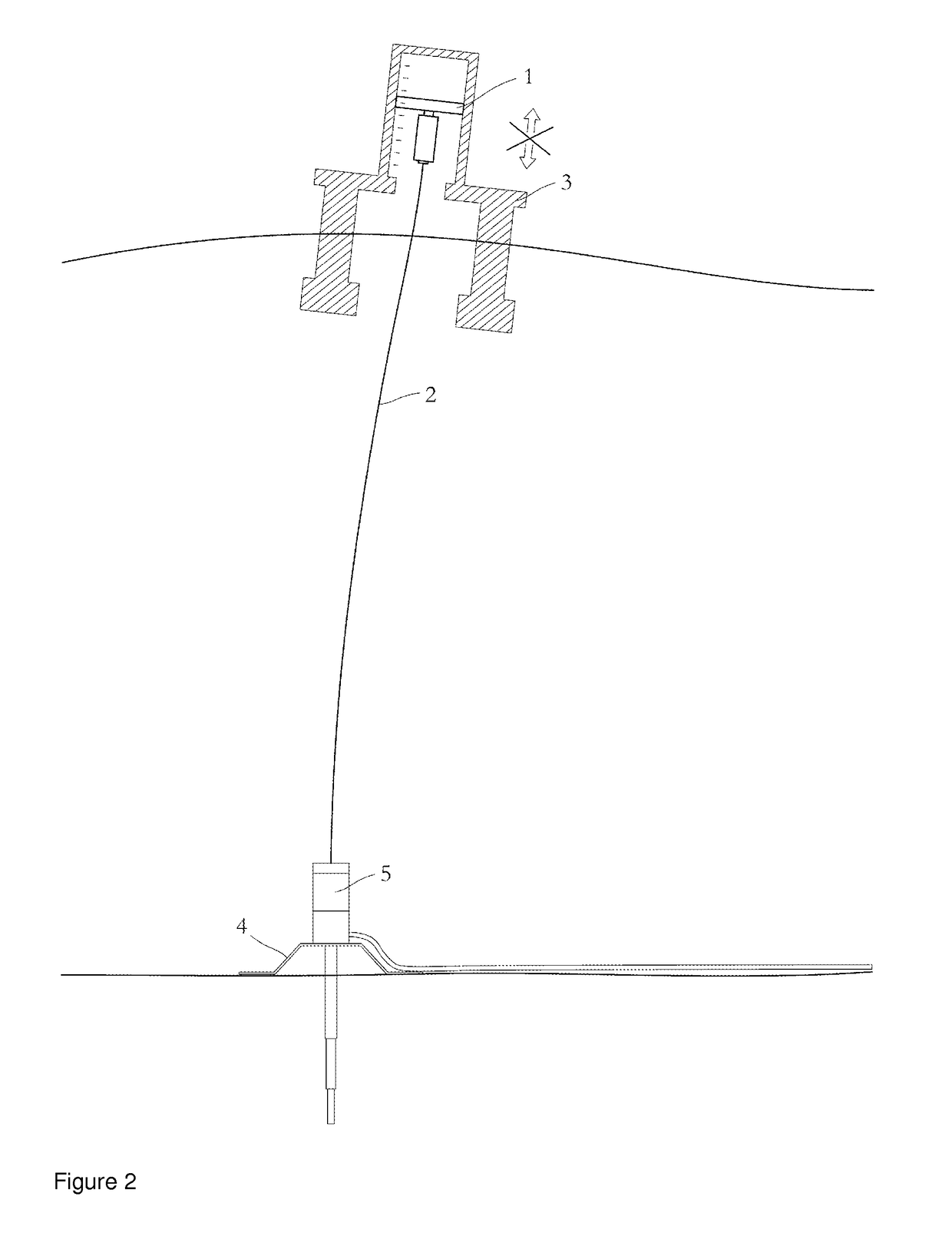
This may result in snag loads and excessive tension forces on the riser 2.
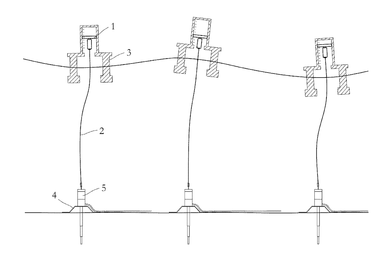
However, one challenge is that during normal operation the vessel 3 may be positioned within a certain operational window above the well on the seabed 4.
For dynamically positioned (DP) vessels, loss of position is normally caused by DP failure or by operator error causing the vessel 3 to drive-off from its intended position.
In a drift-off scenario the vessel either does not have sufficient power to stay in its position given the current weather conditions, or vessel power is lost and the vessel will drift off in the direction of the wind, waves and currents.
Exceeding the load capacity of the well barrier(s) 5 may involve damage of the well head, damage inside the well, damage on the riser 2 etc., all of which are considered to be serious accidental scenarios with high risk towards personnel and the environment.
Damage of the well barrier(s) 5 may result in costly and time consuming repair work, costly delays due to lack of progress in the operation, and last, but not least, environmental and human risks in the form of pollution, blow-outs, explosions, fires, etc.
The ultimate consequence of well barrier damage is a full scale subsea blow-out, with oil and gas from the reservoir being released directly and uncontrollably into the ocean.
If the down-hole safety valve should fail or be damaged in the accident, there are no more means of shutting down the well without drilling a new side well for getting into and plugging the damaged well.
The challenges with existing weak link designs are related to the combination of fulfilling all design requirements (safety factors, etc.) during normal operation of the system, and at the same time ensuring reliable disconnect of the system in an accidental scenario.
It is not uncommon that the weather window for an operation is limited because the weak link can only accommodate a certain vessel offset in normal operation as illustrated by a typical operational diagram shown in FIG. 4.
Therefore, the ability of the weak link to fail due to bending may affect the weather window of the operation.
The effect of internal pressure causes a dilemma in weak link designs based on structural failure:1. The weak link needs to be dimensioned for operation under full pressure with normal safety margins.2. The tension and bending capacity of the well barrier(s) are reduced by internal pressure.3. In some operations the well barrier(s) will be pressurized, but the riser with the weak link will be unpressurised.4. In an accidental scenario the weak link must release before the well barrier(s) is(are) damaged, even when the well barrier(s) is(are) pressurized and the weak link is not pressurized.
Point 4 above is often challenging to achieve in the design of a weak link based on structural failure because the band between minimum capacity in normal operation and maximum break load in an accidental scenario becomes too wide.
In some cases with high pressure system it may not be practically achievable to design a weak link based on structural failure.
In additional, to the technical challenges related to existing weak link solutions based on structural failure, there are also schedule and cost challenges related to the conventional systems.
These qualification programs and the additional requirements for particular material properties are often a challenge with respect to project schedules.
If the combined loads exceed this line there is no guarantee for the integrity of the well barrier(s), and it is likely that the barrier(s) is(are) damaged and possible leaks may occur.

Method used


Image

  • Electronic combined load weak link
  • Electronic combined load weak link
  • Electronic combined load weak link

Examples


Embodiment Construction

[0052]The safety device according to the present invention responds to bending forces in the riser system in addition to tension forces. Furthermore, the device according to the present invention preferably monitors the total combined load including tension, bending, internal pressure and / or temperature effects. All these parameters may continuously be monitored by an autonomous electronic unit 20 which evaluates the combined load on the system and ensures that the combined load is kept within pre-defined allowable limits. The electronic unit 20 compares the evaluated combined load with a pre-defined, limiting combined loading curve developed to protect the well barrier(s) 5 and which will be defined by the calculated relationship between the combined load at the position of the weak link and the combined load capacity curve for the well barrier(s). If the combined load measured exceeds the defined limit curve for the well barrier(s) 5 on the well in question the electronic unit 20 ...


PUM


Abstract

A safety device and method for protection of the integrity of well barrier(s) or other interfacing structure(s) at an end of a riser string or a hose includes a releasable connection in the riser string or hose, the releasable connection arranged to release or disconnect during given predefined conditions in order to protect the well barrier(s) or other interfacing structure(s). The safety device safety device includes at least one sensor to monitor at least one of tension loads, bending loads, internal pressure loads and temperature. The sensor provides measured data relating to at least one of tension loads, bending loads, internal pressure loads and temperature. An electronic processing unit receives and interprets the measured data from the sensor. An electronic, hydraulic or mechanical actuator or switch is arranged to receive a signal from the electronic processing unit and initiate a release or disconnect of the releasable connection.

Description

TECHNICAL FIELD OF INVENTION[0001]The present invention relates to a safety device for emergency disconnect of a riser or hose, typically in relation with well intervention riser systems, completion / work over (C / WO) riser systems etc. The technology / concept may also be applicable for production risers including flexible risers and also offshore offloading systems and other riser or hose systems in use offshore today.BACKGROUND[0002]The conventional riser disconnect systems are based on either an operator initiated emergency disconnect system requiring the active intervention of an operator (by the push of a button) and automatic disconnect systems based on a weak link placed in the riser system which is designed to fail mechanically in an emergency scenario before any other critical components fail. Such disconnect systems are typically referred to as “weak links”.[0003]The key purpose of a weak link is to protect the well barrier(s) or other critical structure(s) interfacing the ri...

Claims


Application Information

Patent Timeline
Patent Type & Authority Patents(United States)
IPC IPC(8): E21B41/00E21B33/038E21B17/01E21B17/06
CPCE21B41/0021E21B17/017E21B17/06E21B33/038E21B17/01
Inventor JENKINS, PETERYSTGAARD, OLAHOLDEN, HARALD
Owner DEN NORSKE STATS OLJESELSKAP AS
Features
  • R&D
  • Intellectual Property
  • Life Sciences
  • Materials
  • Tech Scout
  • Unparalleled Data Quality
  • Higher Quality Content
  • 60% Fewer Hallucinations
Learn More