Circuits and methods for reducing an interference signal that spectrally overlaps a desired signal

a technology of interference signal and circuit, applied in the field of reducing interference signal that, can solve the problems of intentional or unintentional interference of reception devices used in communication, navigation, radar and other sensor applications, and require some time to track

Active Publication Date: 2017-05-16
THE AEROSPACE CORPORATION
View PDF14 Cites 16 Cited by
  • Summary
  • Abstract
  • Description
  • Claims
  • Application Information

AI Technical Summary

Benefits of technology

[0013]Embodiments of the present invention provide circuits and methods for reducing an interference signal that spectrally overlaps a desired signal.
[0038]In some embodiments, the method further includes estimating a signal quality metric; and adaptively adjusting one or more parameters of said linear time domain filter so as to optimize said signal quality metric. In some embodiments, optimizing said signal quality metric minimizes an interference to noise power ratio (INR) or maximizes a carrier power to noise spectral density ratio (C / No) or maximizes a signal power to noise power ratio (SNR).
[0043]In some embodiments, optimizing said signal quality metric minimizes an interference to noise power ratio (INR) or maximizes a carrier power to noise spectral density ratio (C / No) or maximizes a signal power to noise power ratio (SNR).
[0062]Under still another aspect, a method is provided for processing samples of a received signal, the received signal including a desired signal and an interference signal that spectrally overlaps the desired signal. The method can include obtaining amplitudes of the samples of the received signal. The method also can include defining a plurality of clusters, each cluster of the plurality having a corresponding cluster amplitude. The method also can include assigning each sample of a first subset of the samples to one of the clusters based on the amplitude of that sample and based on one or more of the cluster amplitudes. The method also can include suppressing contribution of interference to each sample of the first subset of the samples based on the amplitude of that sample and based on the cluster amplitude of the cluster to which that sample is assigned so as to obtain a processed amplitude of that sample with reduced interference. The method also can include generating an output signal with reduced interference based on the processed amplitudes of the samples of the first subset of the samples.

Problems solved by technology

Receivers used in communication, navigation, radar, and other sensor applications can suffer from intentional or unintentional interference.
While such approaches potentially can work well for narrowband interference, such approaches can fail when the interference signal spectrally overlaps the desired signal, e.g., is spectrally matched to the desired signal or has a bandwidth that overlaps some or all of the desired signal.
Such approaches can require some time to track any interference that changes form or rapidly varies.
Such variation can make it difficult or impossible to reconstruct the interference in a receiver.
Moreover, multiple interferers requires removal of each interferer in the presence of the others making it very difficult to reconstruct precise phase, timing and amplitude of each interferer, One such technique to remove the effects of multiple interferers is successive interference cancellation and will fail when the interferers get too close in amplitude.
Although adaptive antenna-array can be used to null out a matched spectral or overlapping interference signal in the spatial domain, where the signal and interference are separated from one another along different spatial directions, spatial domain nulling and beam-forming approaches can be costly and may not support a vast array of single element receiver implementations, such as handheld receivers.
This adaptive approach requires time to converge, and even then a narrow band signal buried beneath a wide-band strong interference signal might not be recovered because the steady state transfer function is frequency selective.
However, such an approach can be computationally complex, and also relies upon the interference having an approximately constant envelope.
Without prior knowledge of the interferers or if the interferers are too close in power, successive interference cancellation will fail.
Such techniques can be computationally complex and do not work well with multiple interferers due to rapidly increasing complexity as the number of interferers increases.
Unknown signals, such as proprietary waveforms, can render successive interference cancellation or joint demodulators impractical.

Method used


Image

  • Circuits and methods for reducing an interference signal that spectrally overlaps a desired signal
  • Circuits and methods for reducing an interference signal that spectrally overlaps a desired signal
  • Circuits and methods for reducing an interference signal that spectrally overlaps a desired signal

Examples


Embodiment Construction

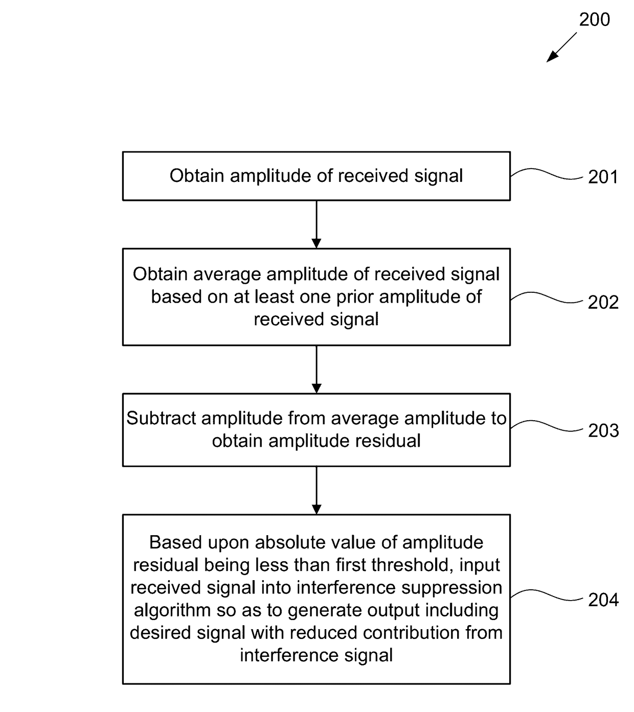
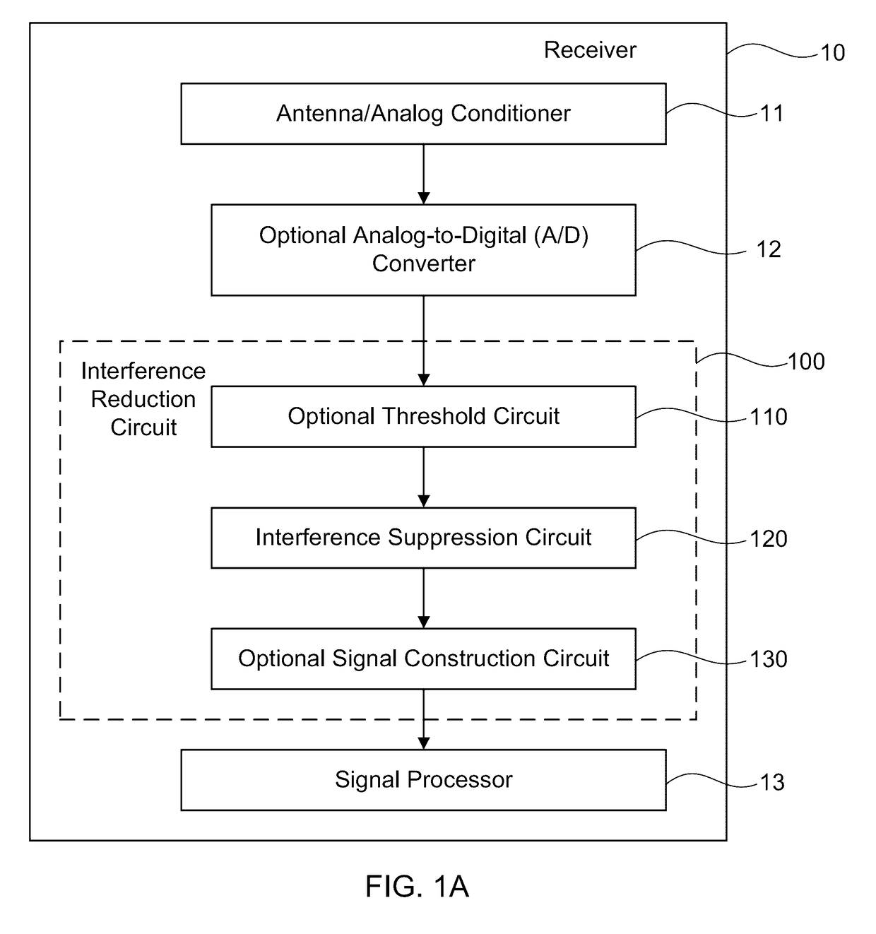
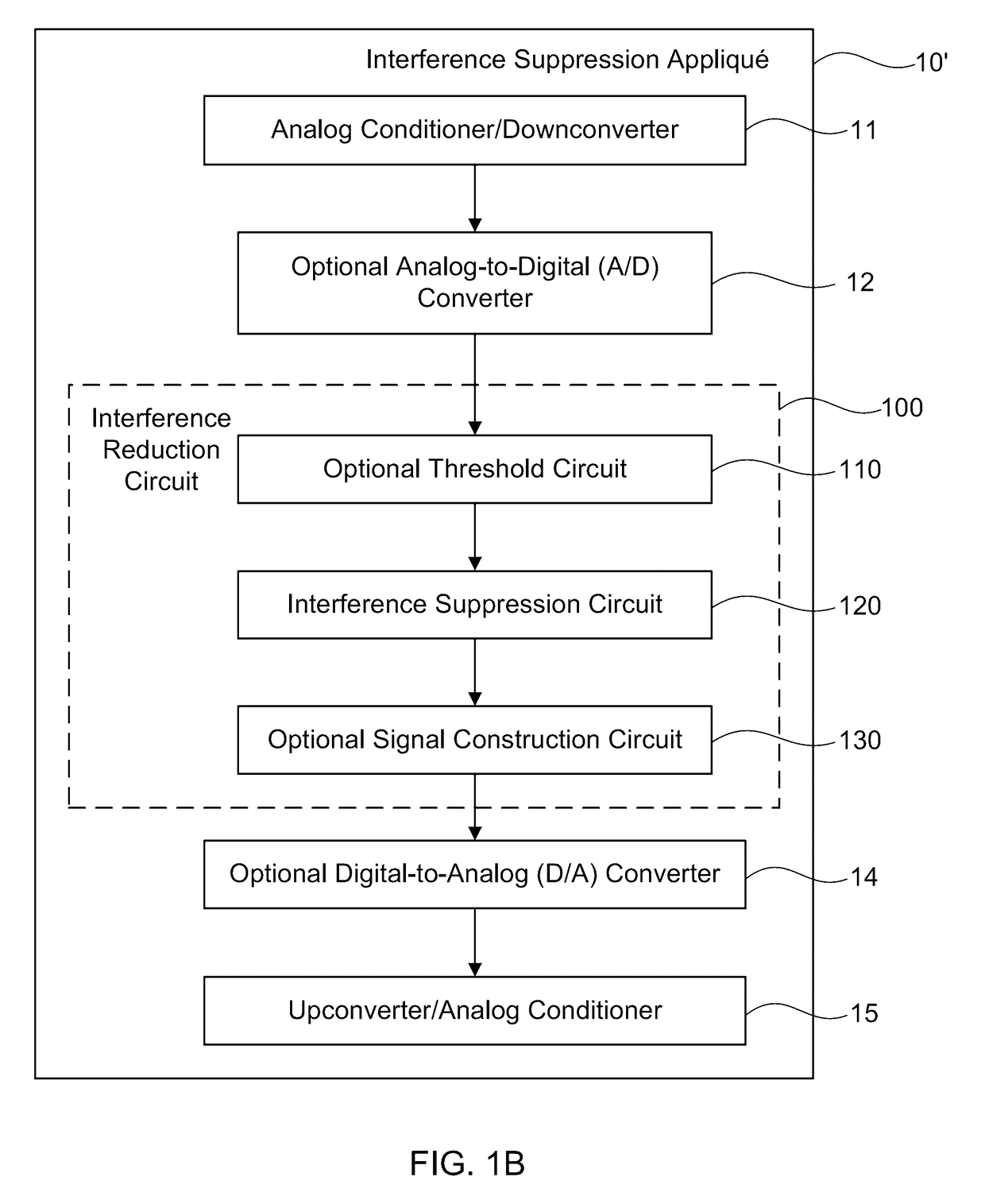
[0128]Embodiments of the present invention provide circuits and methods for reducing an interference signal that spectrally overlaps a desired signal. For example, if the desired signal and the interference signal share a channel, that is, if they spectrally overlap with one another, and if desired signal is much stronger than the interference signal, then the desired signal can be relatively easy to detect and demodulate. However, in some circumstances, the interference signal can make it hard to detect and demodulate the desired signal. As described in greater detail herein, the present circuits and methods need not require detailed knowledge of the desired signal or the interference signal, and as such, readily can be implemented in a variety of practical applications. For example, the present circuits and methods can use any suitable combination of one or more of the interference reduction circuits or methods provided herein so as to provide an output that includes the desired s...


PUM


Abstract

Under one aspect, a method is provided for processing a received signal, the received signal including a desired signal and an interference signal that spectrally overlaps the desired signal. The method can include obtaining an amplitude of the received signal. The method also can include obtaining an average amplitude of the received signal based on at least one prior amplitude of the received signal. The method also can include subtracting the amplitude from the average amplitude to obtain an amplitude residual. The method also can include, based upon an absolute value of the amplitude residual being less than or equal to a first threshold, inputting the received signal into an interference suppression algorithm so as to generate a first output including the desired signal with reduced contribution from the interference signal.

Description

FIELD OF THE INVENTION[0001]This application relates to reducing an interference signal that spectrally overlaps a desired signal.BACKGROUND OF THE INVENTION[0002]Receivers used in communication, navigation, radar, and other sensor applications can suffer from intentional or unintentional interference. In such systems, it can be useful to use signal processing methods to reduce the effects of an interference signal from those of a desired signal.[0003]In some systems, properties of the interference signal are not known a priori. In such cases, it can be desirable to use a blind technique, in which properties of the desired signal also may not necessarily be a priori known. A number of previously known blind single antenna interference suppression methods have been developed in the time domain and frequency-domain of a signal described in the complex in-phase (I) and quadrature (Q) domain. Some interference suppression techniques excise the interference in a domain in which the inter...

Claims


Application Information

Patent Timeline
Patent Type & Authority Patents(United States)
IPC IPC(8): H03D1/04H04B1/10
CPCH04B1/1027H04B1/1036G01S19/21H04B1/7107H04B1/719
Inventor DAFESH, PHILIPHESS, PHILLIP BRIAN
Owner THE AEROSPACE CORPORATION
Why Eureka
Try Eureka