Liquid ejection head and apparatus and method for printing
a liquid ejection head and liquid ejection technology, applied in the direction of printing and inking apparatus, etc., can solve the problems of significantly deviating the landing position of the ejection droplets from the desired landing position, affecting the printing image, and affecting the quality of the printed image, so as to reduce the size of the vortex
- Summary
- Abstract
- Description
- Claims
- Application Information
AI Technical Summary
Benefits of technology
Problems solved by technology
Method used
Image

Examples
first embodiment
[0034]A first embodiment of the present invention will be described hereinbelow with reference to the drawings.
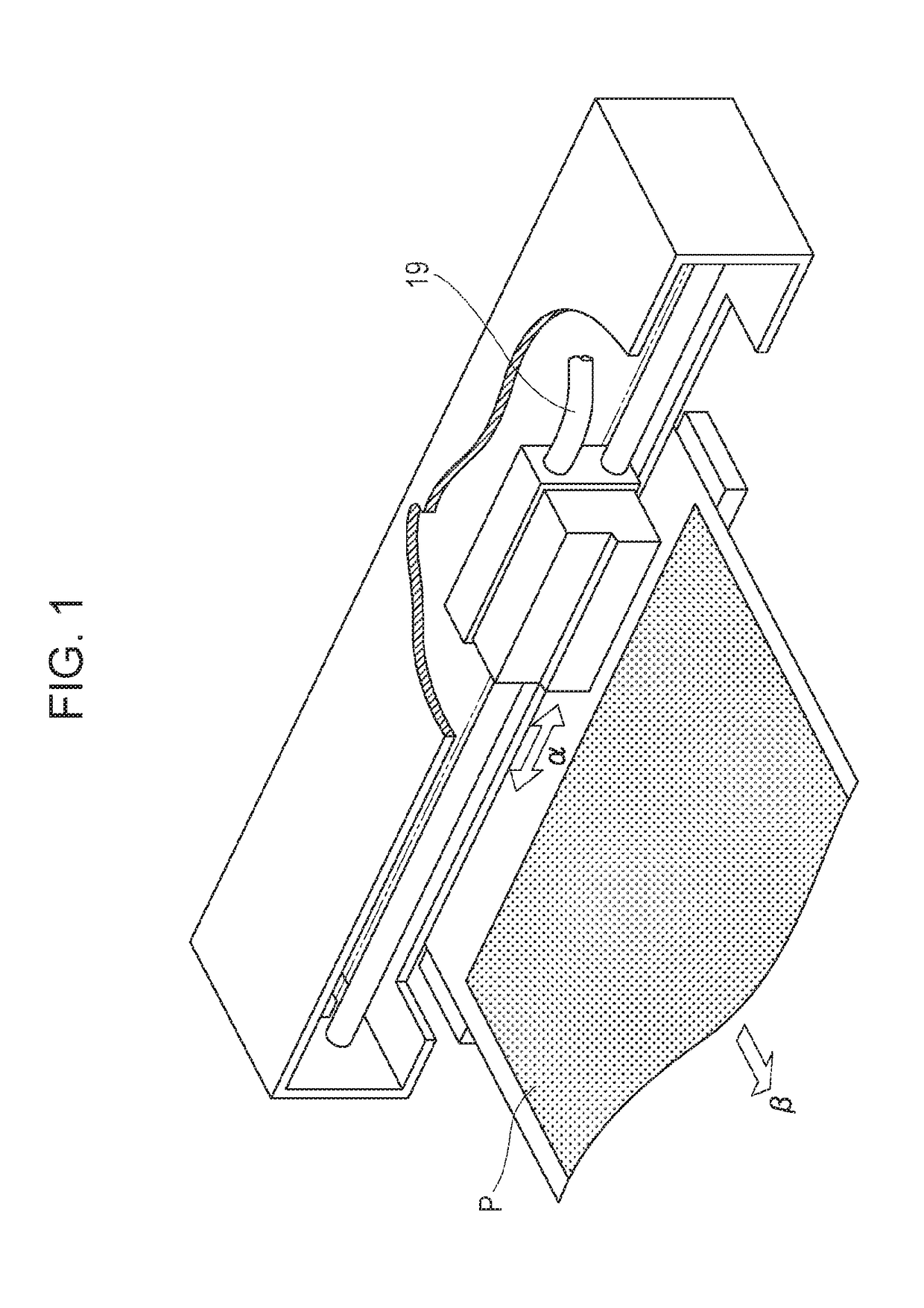
[0035]FIG. 1 is a schematic perspective view of an ink-jet printing apparatus, which is a printing apparatus that ejects liquid, according to the first embodiment. The printing apparatus of this embodiment prints on a printing medium P by alternately repeating the operation of ejecting ink while moving a print head mounted on a carriage back and forth (in the direction of arrow α) on the printing medium P and the operation of conveying the printing medium P in a subscanning direction (in the direction of arrow β). The print head of this embodiment is connected to a gas supply system, described later, with a tube 19, so as to blow gas supplied from the gas supply system.
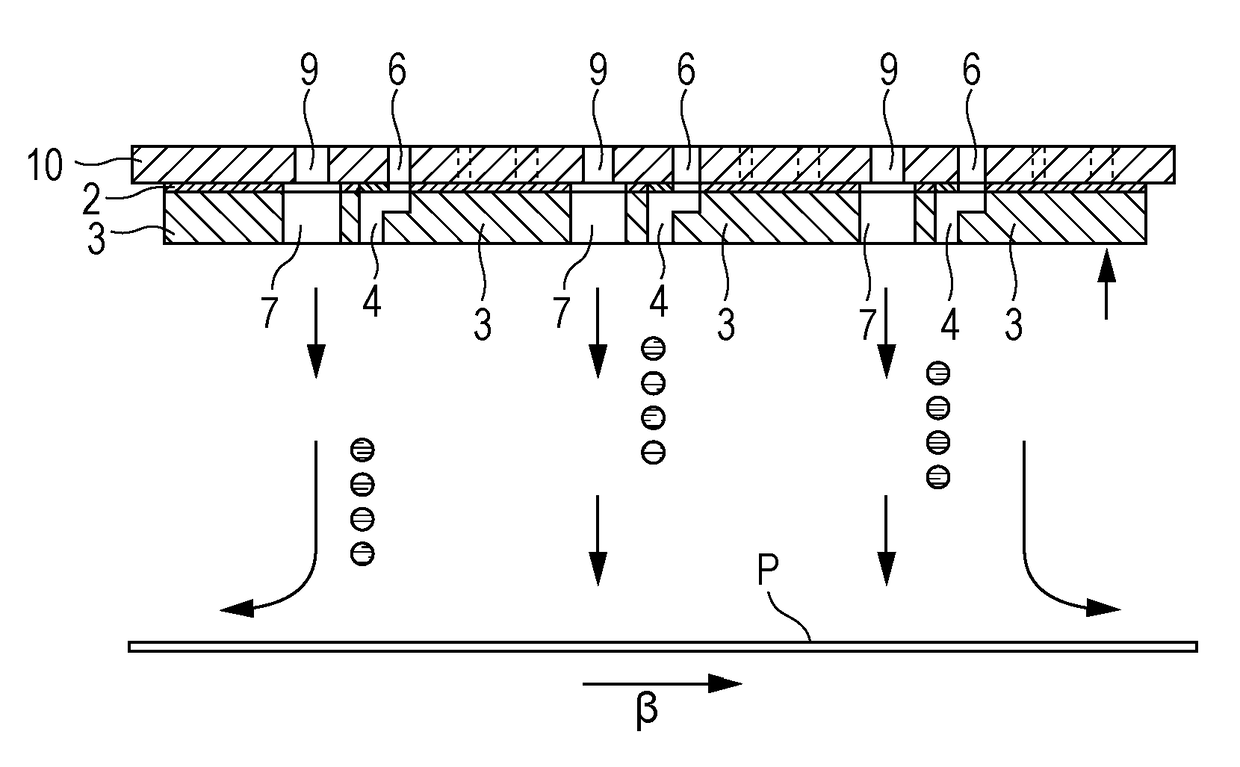
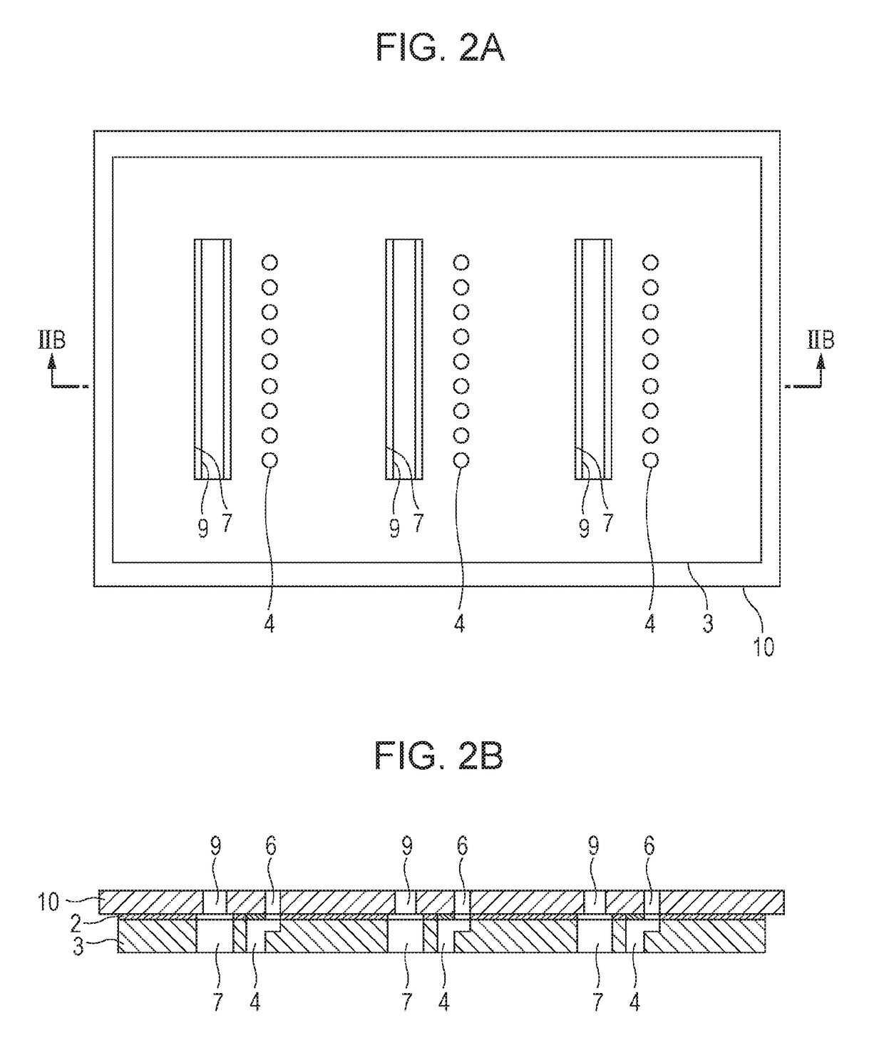
[0036]FIGS. 2A and 2B and FIGS. 3A and 3B illustrate part of a liquid ejection head applicable to this embodiment. FIG. 2A is a plan view of the liquid ejection head viewed from a direction perpendicular to a...
second embodiment
[0051]A second embodiment of the present invention will be described with reference to the drawings. The basic configuration of this embodiment is the same as that of the first embodiment, and therefore only the distinctive configuration of this embodiment will be described.
[0052]FIGS. 7A and 7B are diagrams of an airflow due to the blown gas 14. FIG. 7A illustrates a state in which the gas 14 blown from an area f interferes with the vortex 12 generated due to ejection of droplets. The difference in configuration between this embodiment and the first embodiment is that the blowing position of the gas 14 differs. The area f, which is the blowing position of the gas 14 in this embodiment, is an area on the orifice substrate 3 upstream within the maximum vortex core radius of the vortex 12 from the ejection port array. The range of the blowing speed of the gas 14 blown from the area f will now be described. The range of the blowing speed of the gas 14 is obtained as follows. As shown i...
third embodiment
[0058]A third embodiment of the present invention will be described with reference to the drawings. The basic configuration of this embodiment is the same as that of the first embodiment, and therefore only the distinctive configuration of this embodiment will be described.
[0059]FIGS. 8A and 8B illustrate a liquid ejection head of this embodiment. FIG. 8A is a plan view of the liquid ejection head as viewed from a direction perpendicular to the surface of the orifice substrate 3, and FIG. 8B is a cross-sectional view taken along line VIIIB-VIIIB in FIG. 8A. FIGS. 8A and 8B illustrate an example in which gas blowing ports 7 are provided for ejection port arrays that eject cyan ink.
[0060]As illustrated, the liquid ejection head of this embodiment is characterized by including two gas supply ports 9 for each ejection port array. The gas supply port 9 provided for each ejection port array that ejects cyan ink in FIG. 8B is supplied with gas from the gas supply system (see FIG. 4). The g...
PUM
 Abstract
Description
Claims
Application Information
 - R&D
- Intellectual Property
- Life Sciences
- Materials
- Tech Scout
- Unparalleled Data Quality
- Higher Quality Content
- 60% Fewer Hallucinations
Browse by: Latest US Patents, China's latest patents, Technical Efficacy Thesaurus, Application Domain, Technology Topic, Popular Technical Reports.
© 2025 PatSnap. All rights reserved.Legal|Privacy policy|Modern Slavery Act Transparency Statement|Sitemap|About US| Contact US: help@patsnap.com