Electric motor with coaxial clutch packs that provide differential and torque vectoring

a technology of differential and torque vectoring, applied in the field of electric motors, can solve the problems of significant packaging problems in the supply of hybrid or electric vehicles with slip differential and/or torque vectoring

Active Publication Date: 2017-05-23
BORGWARNER INC
View PDF22 Cites 17 Cited by
  • Summary
  • Abstract
  • Description
  • Claims
  • Application Information

AI Technical Summary

Benefits of technology

[0015]In one or more embodiments, the first planetary gear assembly includes a first sun gear disposed within and enmeshed with a first planet gear set that, in turn, is disposed within and enmeshed with a first ring gear. The second planetary gear assembly includes a second sun gear disposed within and enmeshed with a second planet gear set disposed within and enmeshed with a second ring gear. The rotor couples to the first and second sun gears.
[0016]In one or more embodiments, the first and second ring gears remain stationary and couple to the stationary housing.
[0017]In one or more embodiments, the first planet gear set couples to a first carrier that couples to the first clutch shaft. The first clutch shaft couples the first planet gear set to the first clutch pack. The first clutch pack couples the first clutch shaft to the first output shaft. The first output shaft couples the first clutch pack to a first wheel. Similarly, the second planet gear set couples to a second carrier that couples to the second clutch shaft. The second clutch shaft couples the second planet gear set to the second clutch pack. The second clutch pack couples the second clutch shaft to the second output shaft. The second output shaft couples the second clutch pack to a second wheel.
[0018]In one or more embodiments, the first and second output shafts, the first and second clutch shafts and the first and second sun gears are in coaxially alignment.

Problems solved by technology

However, providing hybrid or electric vehicles with slip differential and / or torque vectoring presents significant packaging problems because there is limited space within the rotor / stator housing of an electric motor.

Method used


Image

  • Electric motor with coaxial clutch packs that provide differential and torque vectoring
  • Electric motor with coaxial clutch packs that provide differential and torque vectoring
  • Electric motor with coaxial clutch packs that provide differential and torque vectoring

Examples


Embodiment Construction

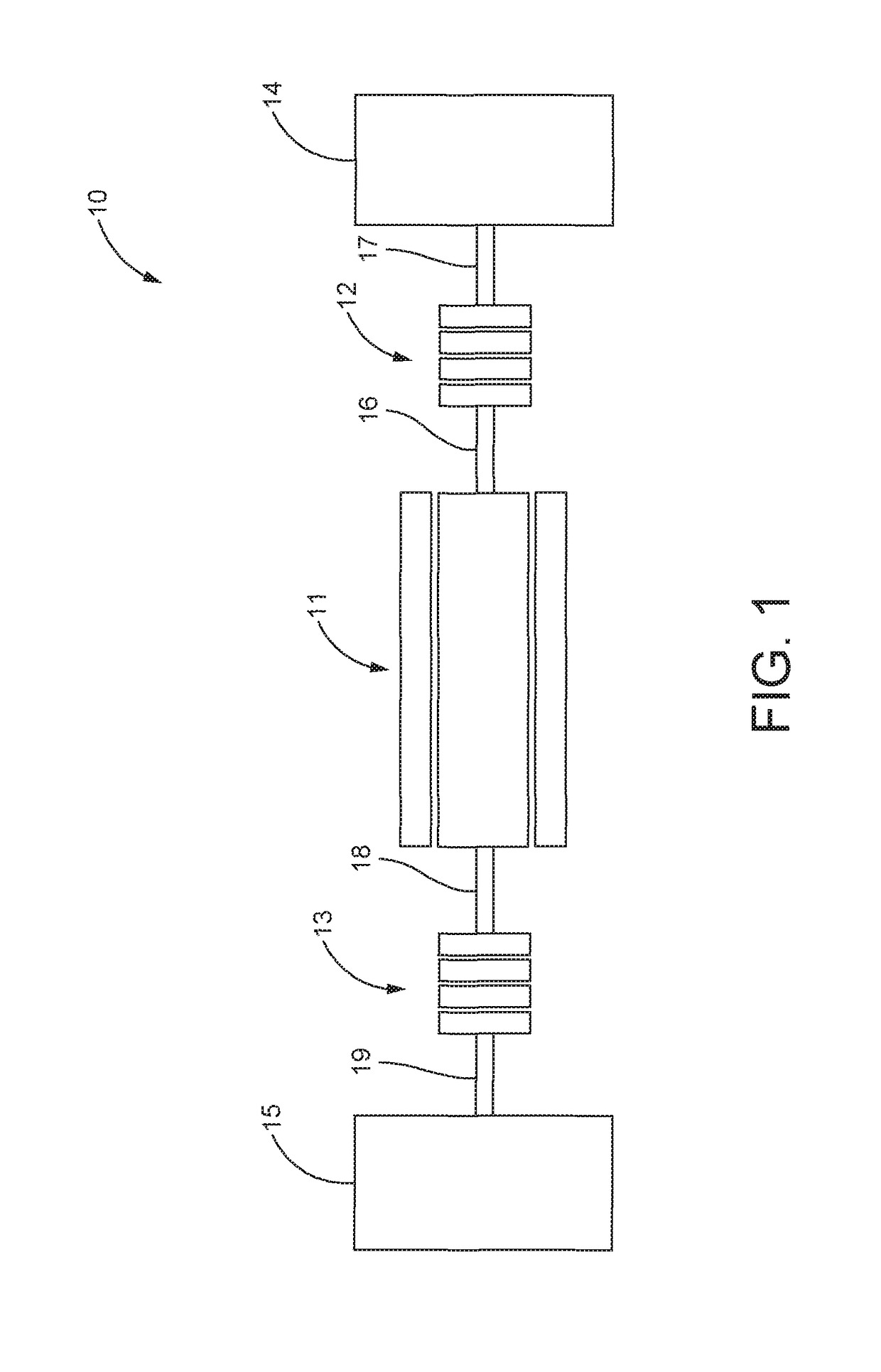
[0025]FIG. 1 illustrates schematically an electric drive system 10 that includes an electric motor 11 coaxially disposed between a first clutch pack 12 and a second clutch pack 13. The first and second clutch packs 12, 13, as well as the electric motor 11, are coaxially disposed between a first traction member or wheel 14 and a second traction member or wheel 15. A first clutch shaft 16 couples the electric motor 11 to the first clutch pack 12 and a first output shaft 17 couples the first clutch pack 12 to the first wheel 14. Meanwhile, a second clutch shaft 18 couples the electric motor 11 to the second clutch pack 13 and a second output shaft 19 couples the second clutch pack 13 to the second wheel 15.

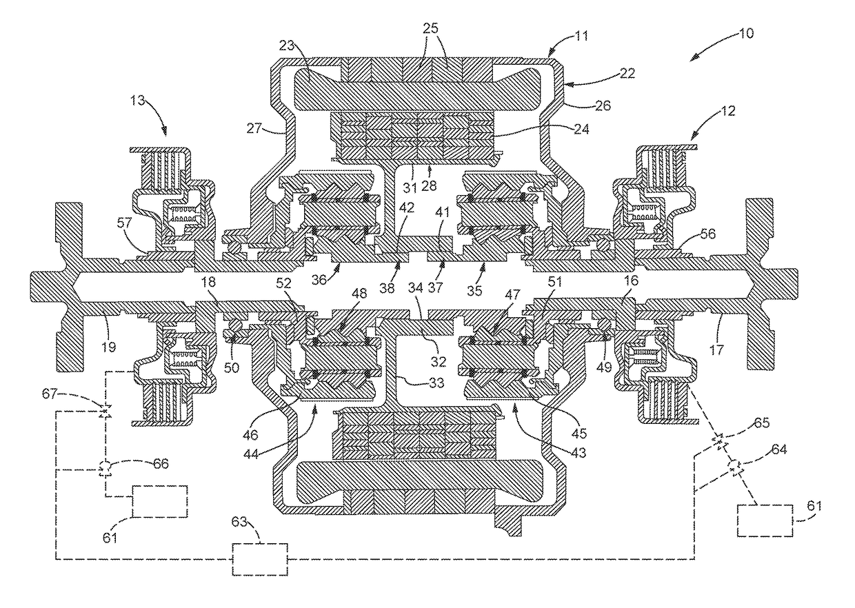
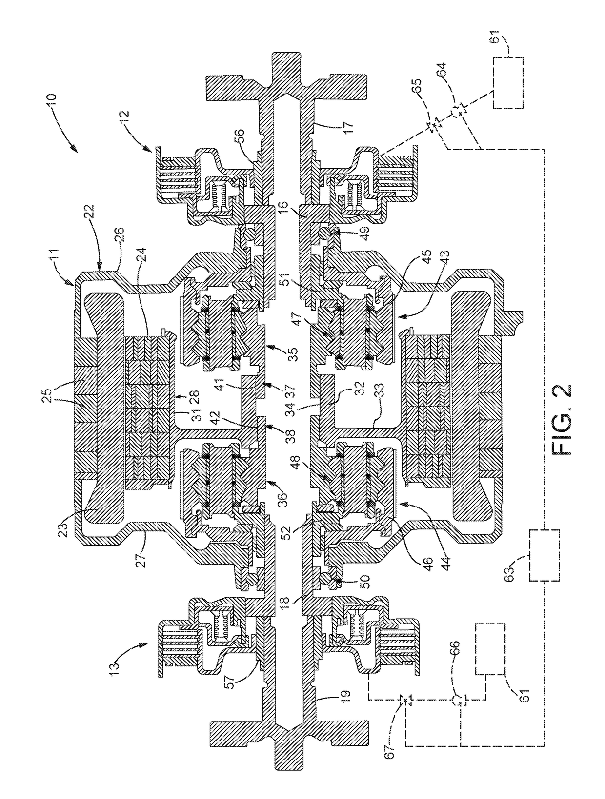
[0026]FIG. 2 is a sectional view of one embodiment of the electric drive system 10. A electric motor 11 includes a housing 22 that surrounds a stator 23 that, in turn, surrounds a rotor 24. The rotor 24 rotates within the stator 23, which is stationary and may connect to the housing ...


PUM


Abstract

An electric drive system for a vehicle includes an electric motor with a stator disposed circumferentially around a rotor. The rotor connects to a support frame that extends radially inwards to couple the rotor to a first planetary gear assembly and a second planetary gear assembly. The stator, rotor and the first and second planetary gear assemblies are disposed within a stationary housing. The first and second planetary gear assemblies couple to first and second clutch packs respectively, that are disposed outside of the stationary housing.

Description

BACKGROUND[0001]Technical Field[0002]This disclosure relates generally to electric motors for powering vehicles. More specifically, this disclosure relates to an electric motor disposed coaxially between a pair of clutch packs. Each clutch pack coaxially connects to and provides differential and torque vectoring to a wheel or traction member.[0003]Description of the Related Art[0004]Motor vehicles have traditionally employed internal combustion (IC) engines with a mechanical or hydraulic transmission system. Hybrid vehicles utilize a combination of an IC engine that powers one axle and an electric motor that powers the other axle. Fully electric cars are now available, some with electric motors mounted perpendicular to the axles, others with electric motors mounted parallel to or coaxially with one or both axles. One advantage of using electric motors for powering vehicles is that there are no combustion products to treat before emission to the atmosphere. Another advantage is that ...

Claims


Application Information

Patent Timeline
Patent Type & Authority Patents(United States)
IPC IPC(8): F16H48/10F16H48/22B60K17/16B60K23/08B60K23/04
CPCF16H48/22F16H48/10B60K17/16B60K23/0808F16H2048/104F16H2048/106B60K2023/043B60K1/00B60K2001/001B60K17/046B60K23/04
Inventor MORGAN, THOMAS
Owner BORGWARNER INC
Why Eureka
Try Eureka