Contact assembly in a testing apparatus for integrated circuits

a technology of contact assembly and testing apparatus, applied in the field of electric contacts, can solve the problems of loss/reduction of contact, poor co-planarity, and high temperature of the testing apparatus, and achieve the effects of quick and easy customization, and less effect on the position of contact pins

Active Publication Date: 2017-05-23
JF MICROTECH
View PDF2 Cites 0 Cited by
  • Summary
  • Abstract
  • Description
  • Claims
  • Application Information

AI Technical Summary

Benefits of technology

[0016]Another advantage of the present invention is that it does not require the rectangular assembly of the four rigid shafts to engage with the housing walls of the testing apparatus, so that movement or positional changes of the testing apparatus will have a much lesser effect on the position of the contact pins.
[0017]The present invention also relates to a feature that allows easier assembly of the above-mentioned rectangular assemblies into a housing of the testing apparatus. This is done by having a dowel pin through-hole at one end of each rigid shaft. As the rectangular assemblies are lowered into the housing cavity of a testing apparatus, each through-hole is aligned with a dowel pin located on the housing, so that accurate assembly is assured. Further, the placement of the through-holes on each batch of rigid shafts can be changed for quick and easy customization of contact pin configurations.
[0018]Yet another advantage of the present invention is thus the ease of changing faulty pins that is inherent in the assembly design. Any faulty contact pin is easily replaced by simply removing the rectangular assembly from the apparatus housing, separating the rigid shaft that holds the faulty pin, and replacing the faulty pin. Once the pin is replaced, the rigid shafts are again joined with each other to form the rectangular assembly, and then lowered into the apparatus housing. The precision of each contact pin is maintained due to the design of this assembly.
[0019]The present invention further relates to a method of assembling the above electrical contact assembly. This method comprises the steps of:
[0020]a) sliding a rigid shaft through a matching through-opening of a contact pin, until the contact pin reaches an intermediate point along the rigid shaft;
[0021]b) sliding the rigid shaft through a matching through-opening of an electrical insulator, until the electrical insulator rests next to the contact pin along the rigid shaft;

Problems solved by technology

Testing at these higher power levels result in higher temperatures within the testing apparatus.
High temperatures can cause expansion of only certain parts of the apparatus, due to different materials being used in different parts of the design, and this can then lead to stack-up issues such as poor co-planarity, loss / reduction of contact due to offset of contact pins, and uneven contact pins, among others.
Although solutions utilizing cantilever pins exist for high current / power IC device testing, the designs of the contact pin assembly make the testing apparatus prone to the above faults and disadvantages.

Method used


Image

  • Contact assembly in a testing apparatus for integrated circuits
  • Contact assembly in a testing apparatus for integrated circuits
  • Contact assembly in a testing apparatus for integrated circuits

Examples


Embodiment Construction

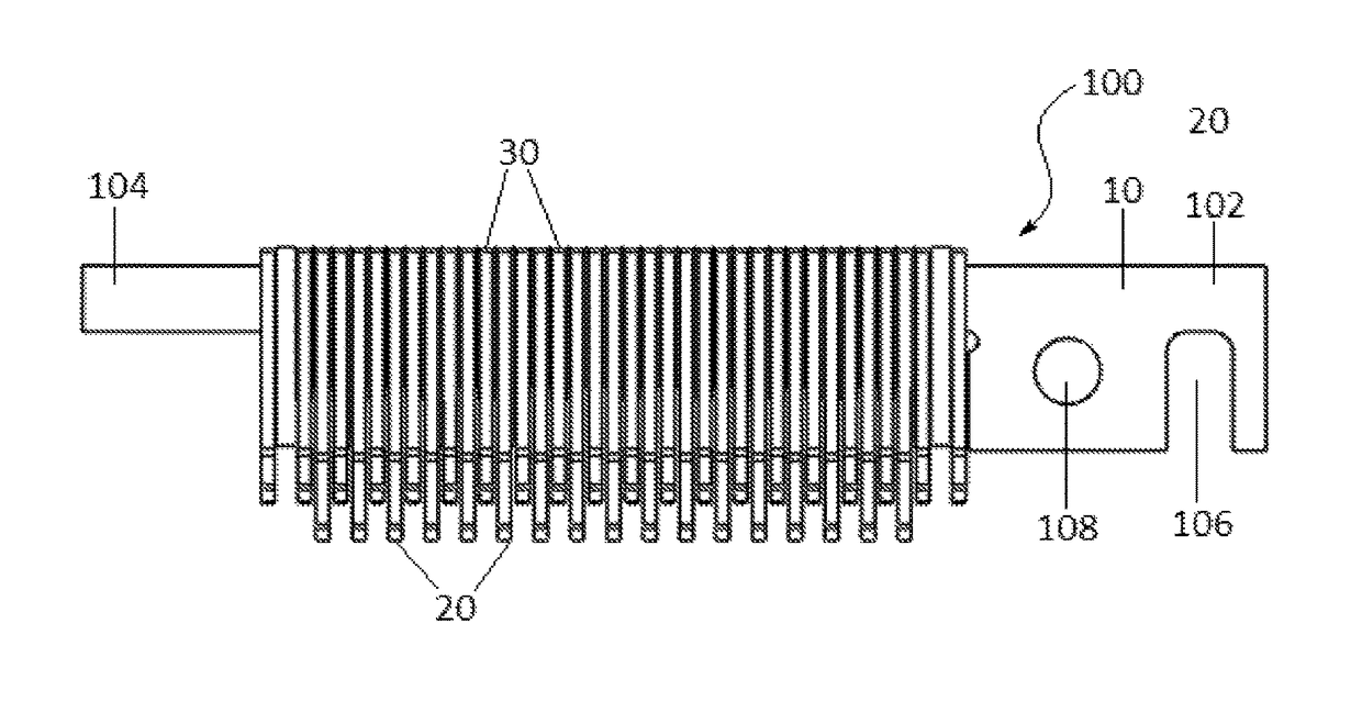
[0040]It should be noted that the following detailed description is directed to an electrical contact assembly of an integrated circuit (IC) testing apparatus, and is not limited to any particular size or configuration but in fact a multitude of sizes and configurations within the general scope of the following description.

LIST OF NUMBERED ELEMENTS IN FIGURES

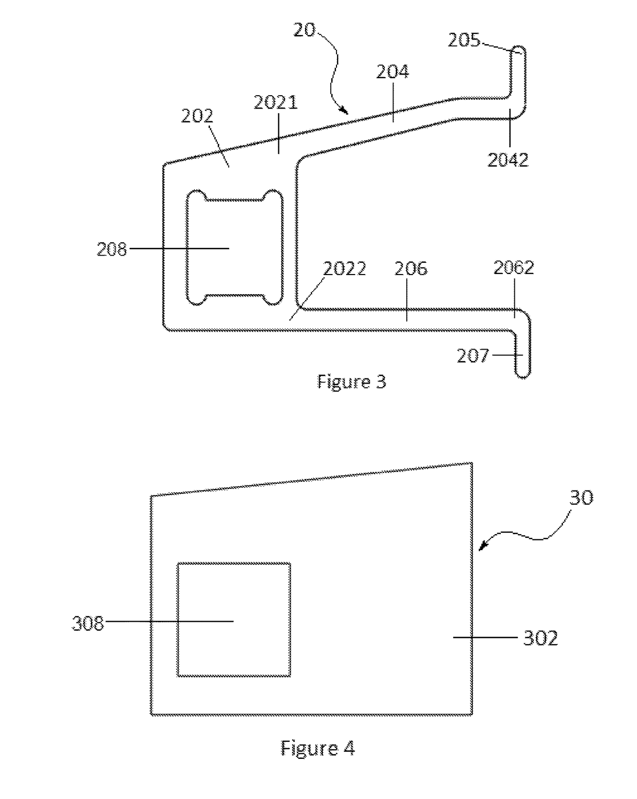
[0041]Rigid shaft (10)[0042]Rigid shaft sub-assembly (100)[0043]First end of rigid shaft (102)[0044]Second end of rigid shaft (104)[0045]Notch (106)[0046]Dowel pin through-hole (108)[0047]Contact pin (20)[0048]Contact pin base portion (202)[0049]First side of base portion (2021)[0050]Second side of base portion (2022)[0051]Cantilever arm (204)[0052]Cantilever arm end (2042)[0053]First contact portion (205)[0054]Stationary arm (206)[0055]Stationary arm end (2062)[0056]Second contact portion (207)[0057]Through-opening of contact pin (208)[0058]Electrical insulator (30)[0059]Electrical insulator base portion (302)[0060]Through-open...


PUM


Abstract

An electrical contact assembly for use in an integrated circuit testing apparatus having a plurality of electrical contact pins and electrical insulators that are each fashioned with through-openings that match a cross-section of a rigid shaft so that the rigid shaft can be threaded through the contact pins and insulators. This ensures that the position of each contact pin is substantially aligned in a single datum with other contact pins following the datum of the rigid shaft. The electrical insulators are placed between each contact pin to prevent electrical connection between contact pins. Further, four rigid shafts assembled in this manner may be interlocked with each other to form a rectangular assembly, which can be inserted into an appropriate housing of the testing apparatus.

Description

FIELD OF INVENTION[0001]The present invention relates generally to electrical contacts, and more specifically to an electrical contact assembly in an integrated circuit testing apparatus.BACKGROUND OF INVENTION[0002]In certain branches of integrated circuit (IC) device testing, besides the usual requirements of speed and reliability, the power and temperature handling capacity of the testing apparatus is of key importance. Ease of maintenance and replacement of contact pins are also important factors, as these keep productivity levels up.[0003]Testing at these higher power levels result in higher temperatures within the testing apparatus. High temperatures can cause expansion of only certain parts of the apparatus, due to different materials being used in different parts of the design, and this can then lead to stack-up issues such as poor co-planarity, loss / reduction of contact due to offset of contact pins, and uneven contact pins, among others.[0004]Cantilever contact pins are kn...

Claims


Application Information

Patent Timeline
Patent Type & Authority Patents(United States)
IPC IPC(8): G01R31/00G01R3/00G01R1/073
CPCG01R3/00G01R1/07307G01R1/07371
Inventor FOONG, WEI KUONGGOH, KOK SINGMUNDIYATH, SHAMALLEE, ENG KIAT
Owner JF MICROTECH
Why Eureka
Try Eureka