
Devices, systems and methods for ultrafast optical applications

a technology of ultrafast optical applications and devices, applied in non-linear optics, instruments, optics, etc., can solve the problems of long interaction lengths, large switching energies and/or long interaction lengths to produce significant effects, and complicate the incorporation of these materials into active optical devices, so as to increase the thermal nonlinearity of the second metallic layer, increase the nonlinear optical response, and increase the linear absorption in the second metallic layer.

Active Publication Date: 2017-05-23
GEORGIA TECH RES CORP
View PDF4 Cites 6 Cited by
  • Summary
  • Abstract
  • Description
  • Claims
  • Application Information

AI Technical Summary

Benefits of technology

The proposed structure achieves significantly larger nonlinear optical responses compared to single metallic layers, with reflectance changes exceeding 10% at lower fluences, enabling efficient ultrafast optical control and reducing the sensitivity to changes in the imaginary part of the refractive index, thus addressing the limitations of existing devices.

Problems solved by technology

The nonlinear optical response of a material is strong when the optical field resonates with the frequency of an allowed electronic transition, but this also leads long-lived excitations that are much slower than electronic processes that induce a nonlinear polarization.
However, in all cases, since the nonlinear response of common materials is typically weak, when incorporated in device configurations they require large switching energies and / or long interaction lengths to produce significant effects.
In addition to these restrictions, other restrictions such as fulfillment of wave-vector matching conditions further complicate the incorporation of these materials into active optical devices.
Noble metals are known to have an extremely large and ultrafast NLO response in the visible spectral range, much larger than most known organic or inorganic materials, but are seldom used as NLO materials due to their limited optical transparency and large reflectance in the visible (Vis) and near infrared (NIR) spectral ranges.

Method used


Image

  • Devices, systems and methods for ultrafast optical applications
  • Devices, systems and methods for ultrafast optical applications
  • Devices, systems and methods for ultrafast optical applications

Examples


Embodiment Construction

[0079]To facilitate an understanding of the principles and features of the various embodiments of the invention, various illustrative embodiments are explained below. Although exemplary embodiments of the invention are explained in detail, it is to be understood that other embodiments are contemplated. Accordingly, it is not intended that the invention is limited in its scope to the details of construction and arrangement of components set forth in the following description or illustrated in the drawings. The invention is capable of other embodiments and of being practiced or carried out in various ways. Also, in describing the exemplary embodiments, specific terminology will be resorted to for the sake of clarity.

[0080]It must also be noted that, as used in the specification and the appended claims, the singular forms “a,”“an” and “the” include plural references unless the context clearly dictates otherwise. For example, reference to a component is intended also to include composit...


PUM

PropertyMeasurementUnit
thickaaaaaaaaaa
thickaaaaaaaaaa
thickaaaaaaaaaa

Abstract

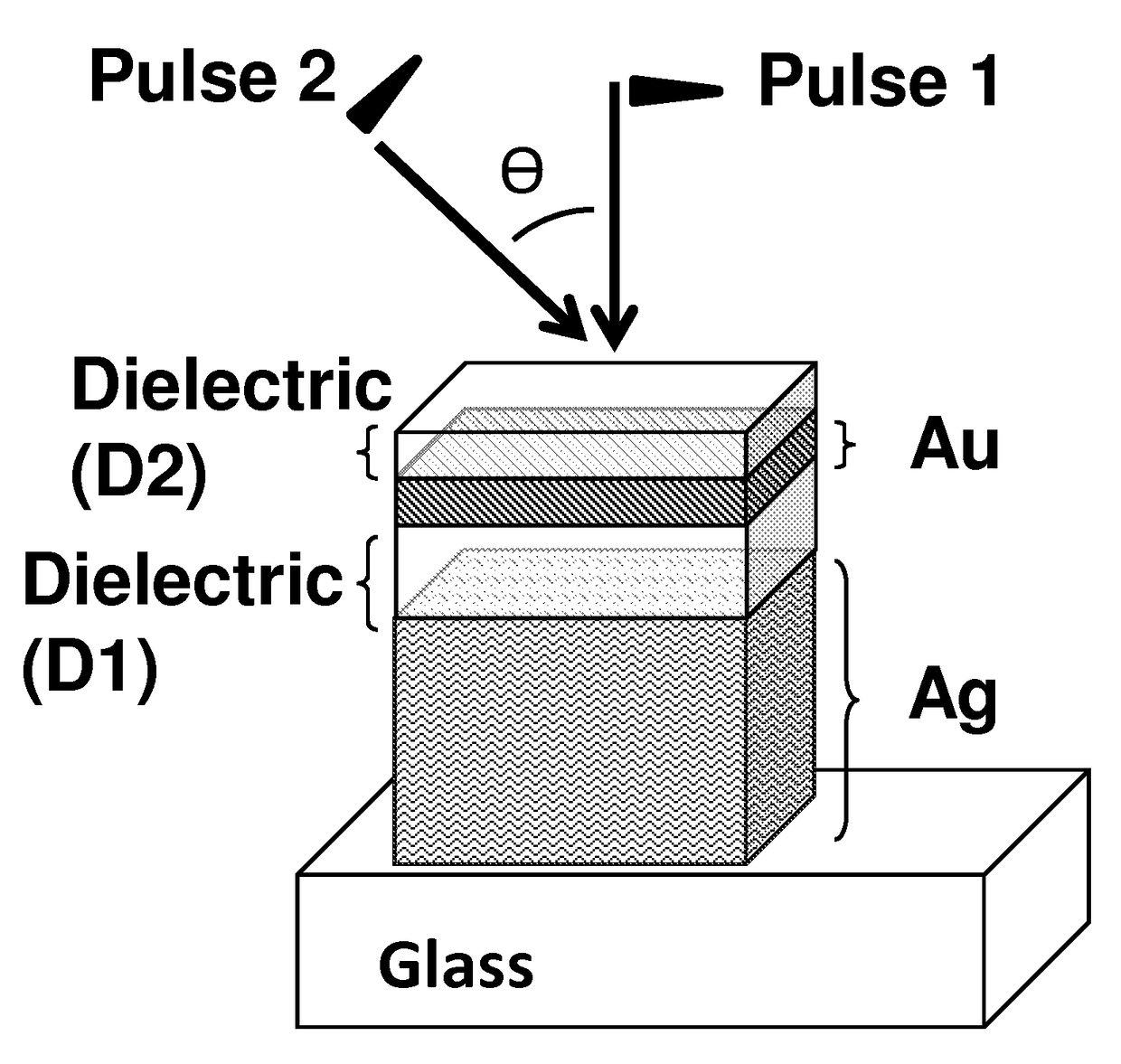
An optical device capable of an ultrafast and large change of its reflection or absorption coefficient upon being excited by an ultrafast optical pulse with wavelength in the visible, near-infrared, or infrared spectral regions. The optical device includes, in sequential order, a first thick metallic layer, a first dielectric layer, a second thin metallic layer, and a second dielectric layer. The optical device acts as a nonlinear mirror that presents a large reflectance at low irradiance and a low reflectance at large irradiance. The optical device can further act as a nonlinear mirror that presents a linear and nonlinear reflectance with a large angular bandwidth.

Description

CROSS-REFERENCE TO RELATED APPLICATIONS[0001]This application is a U.S. National Stage of International Application No. PCT / US2013 / 077166, filed 20 Dec. 2013, which claims the benefit of U.S. Provisional Application No. 61 / 739,071 filed 19 Dec. 2012, U.S. Provisional Application No. 61 / 831,292 filed 5 Jun. 2013, and International Application No. PCT / US2013 / 07672, filed 19 Dec. 2013, the entire contents and substance of which are hereby incorporated by reference.STATEMENT OF FEDERALLY SPONSORED RESEARCH[0002]This technology was made with government support under contract 0120967 awarded by the National Science Foundation (NSF), contract DMR-0120967 awarded by the NSF, and contract W31P4Q-09-1-0012 awarded by the US Army. The government has certain rights in the technology.BACKGROUND OF THE INVENTION[0003]1. Field of the Invention[0004]The present invention relates generally to devices, systems and methods for ultrafast optical applications, and more specifically to a nonlinear optica...

Claims


Application Information

Patent Timeline
Patent Type & Authority Patents(United States)
IPC IPC(8): G02F1/03G02F1/19G02F1/35G02F1/17G02F1/01G02F1/21G02F1/355
CPCG02F1/21G02F1/0126G02F1/17G02F1/19G02F1/3523G02F1/355G02F2001/211G02F2203/10G02F1/211
Inventor KIPPELEN, BERNARDFUENTES-HERNANDEZ, CANEKHSU, JAMES JUNE FAN
Owner GEORGIA TECH RES CORP
Learn More