Stepping inductor for fast transient response of switching converter

a technology of switching converters and inductor ripple currents, which is applied in the direction of power conversion systems, dc-dc conversion, climate sustainability, etc., can solve the problems of inherently limited transient output response to a fast load change, limited inherent response of converters, and all proposed solutions have limitations. achieve the effect of improving converter dynamic response, low output inductor ripple current, and fast dynamic respons

Inactive Publication Date: 2004-04-29
THE UNIVERSITY OF HONG KONG
View PDF4 Cites 20 Cited by
  • Summary
  • Abstract
  • Description
  • Claims
  • Application Information

AI Technical Summary

Benefits of technology

0011] Accordingly, it is an object of the present invention to provide fast dynamic response to switching power converters.
0012] It is another object of the present invention to maintain low output inductor ripple current.
0013] It is another object of the pres...

Problems solved by technology

Switching converters are widely used to provide high efficiency and light weight power supply, however the transient output response to a fast load change is inherently limited by the output inductor that is present in most switching power converters.
However, the inherent response of the converter is limited by the output filter which is largely determined by the value of the output inductor.
Many researchers in the field have attempted to enable fast response through several different methods but all of the proposed solutions have limitations.
However, this approach brought on...

Method used


Image

  • Stepping inductor for fast transient response of switching converter
  • Stepping inductor for fast transient response of switching converter
  • Stepping inductor for fast transient response of switching converter

Examples


first embodiment

[0029] First Embodiment

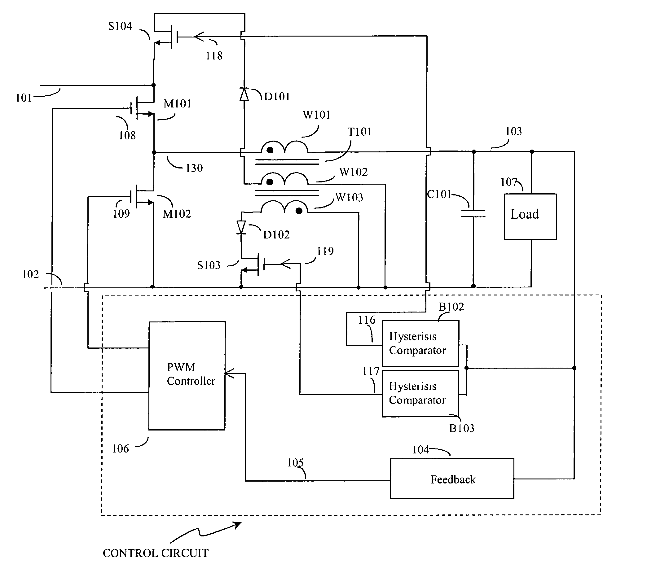
[0030] FIG. 3 illustrates basic the circuit of the first embodiment of the invention, which comprises a power circuit and a control circuit. The power circuit comprises a pair of input terminals 101 and 102 for connection to a DC voltage source. It further comprises a pair of switches, represented by MOSFETs M101 and M102, which produce a series of alternating voltage pulses at node 130. This pair of switches is coupled to a transformer T101, which comprising windings W101, W102 and W103, and an output capacitor C101, as indicated in FIG. 3. A load is connected to the output capacitor C101. Winding W101 is coupled directly to capacitor C101. Winding W102 is coupled to the input voltage source and the voltage produced by the voltage drop of the MOSFET S104 and diode D101. Winding W103 is coupled to an input voltage source and the voltage source produced by the voltage drop of the MOSFET S103 and diode D102. Two MOSFETs S103 and S104 control the connection of vo...

second embodiment

[0042] Second Embodiment

[0043] FIG. 6 illustrates a second embodiment of the present invention, which synchronizes the switch on and switch off time of switches M201, N202, S203 and S204, in order to achieve faster response. This embodiment also comprises a power circuit and a control circuit, similar to the first embodiment.

[0044] The power circuit comprises a pair of input terminals 201 and 202 for connection to a DC voltage source, and further comprises a pair of switches, represented by MOSFETs M201 and M202, which produces a series of alternating voltage pulses at node 230. This pair of switches is coupled to a transformer T201, which comprises windings W201, W202 and W203, and an output capacitor C201, as indicated in FIG. 6. A load is connected to the output capacitor C201, and winding W201 is coupled directly to capacitor C201. Windings W202 is coupled to a input voltage source and the voltage source caused by the voltage drop of the MOSFET S204 and diode D201. Windings W203...

third embodiment

[0050] Third Embodiment

[0051] FIG. 7 illustrates a third embodiment of the present invention, which eliminates the need for the transformer to carry both the steady state output current and transient current. The steady state current is handled by a parallel inductor while the transient current is handled by a separate transformer. This increases the flexibility for the construction of the inductor and allows better control of parameters. This embodiment also comprises a power circuit and a control circuit similar to the first embodiment.

[0052] The power circuit comprises a pair of input terminals 301 and 302 for connection to a DC voltage source, and further comprises a pair of switches, represented by MOSFETs M301 and M302, which produces a series of alternating voltage pulses at node 330. This pair of switches is coupled to a transformer T301, which comprises windings W301, W302 and W303, and an output capacitor C301, as illustrated in FIG. 7. A load is connected to the output ca...


PUM


Abstract

A fast transient response converter is disclosed which makes use of stepping inductor in a switching converter to speed up output voltage response under fast transient condition. The inductive element in a switching converter is replaced by two series or parallel inductive elements, one of which has a smaller value of inductance than the other. During the fast transient period, the inductor with larger inductance value will be shorted to a voltage source. The total inductance will be greatly reduced and thus allows rapid current change during the transient change.

Description

1. FIELD OF THE INVENTION[0001] This invention relates to the field of switch mode power converters, and in particular fast dynamic response of power converters.2. BACKGROUND OF THE INVENTION[0002] Switching converters are widely used to provide high efficiency and light weight power supply, however the transient output response to a fast load change is inherently limited by the output inductor that is present in most switching power converters. A typical prior art buck converter comprises a power stage with a plurality of switches, an inductor-capacitor filter and a feedback circuit. This feedback circuit monitors the converter output voltage and controls Pulse Width Modulation (PWM) of the switches. When there is a fast dynamic load change the response of the converter is limited by two parts of the converter, namely the feedback circuit and the power stage. The feedback circuit can be designed to be very fast by traditional linear approach or non-linear approach. However, the inh...

Claims


Application Information

Patent Timeline
IPC IPC(8): H02M1/15H02M3/158
CPCH02M1/15H02M3/158Y02B70/1466Y02B70/1425H02M3/1588Y02B70/10
Inventor POON, FRANKI NGAI KITPONG, MAN HAYLIU, JOE CHUI PONG
Owner THE UNIVERSITY OF HONG KONG
Why Eureka
Try Eureka