Fire and water resistant expansion joint system

Active Publication Date: 2017-06-06
EMSEAL JOINT SYST
View PDF433 Cites 67 Cited by
  • Summary
  • Abstract
  • Description
  • Claims
  • Application Information

AI Technical Summary

Benefits of technology

[0020]The expansion joint systems and architectural joint systems of the present invention provide a substantially resilient fire resistant and water resis

Problems solved by technology

However, interior horizontal joints may also be subject to pedestrian traffic and in some cases vehicular traffic as well.
It has been generally recognized that building joint systems are deficient with respect to fire resistance.
In some instances, movement as a result of building joint systems has been shown to create chimney effects which can have consequences with regard to fire containment.
This often results in the subversion of fire resistive elements that may be incorporated into the construction of a building.
This problem is particularly severe in large high-rise buildings, parking garages, and stadiums where fire may spread too rapidly to allow the structures to be evacuated.
Where movements were larger and the materials were significantly compressed during the normal thermal expansion cycles of the building structure, these designs generally did not function as intended.
Indeed, many designs simply lacked the resilience or recovery characteristics required to maintain adequate coverage of the entire joint width throughout the normal thermal cycle (expansion and contraction) that buildings experience.
These designs do not have fire resistant properties in a sufficient fashion to meet even the lowest fire rating standards.
Indeed, many waterproofing materials act as fuel for any fire present, which can lead to a chimney effect that rapidly spreads fire throughout a building.

Method used


Image

  • Fire and water resistant expansion joint system
  • Fire and water resistant expansion joint system
  • Fire and water resistant expansion joint system

Examples


Embodiment Construction

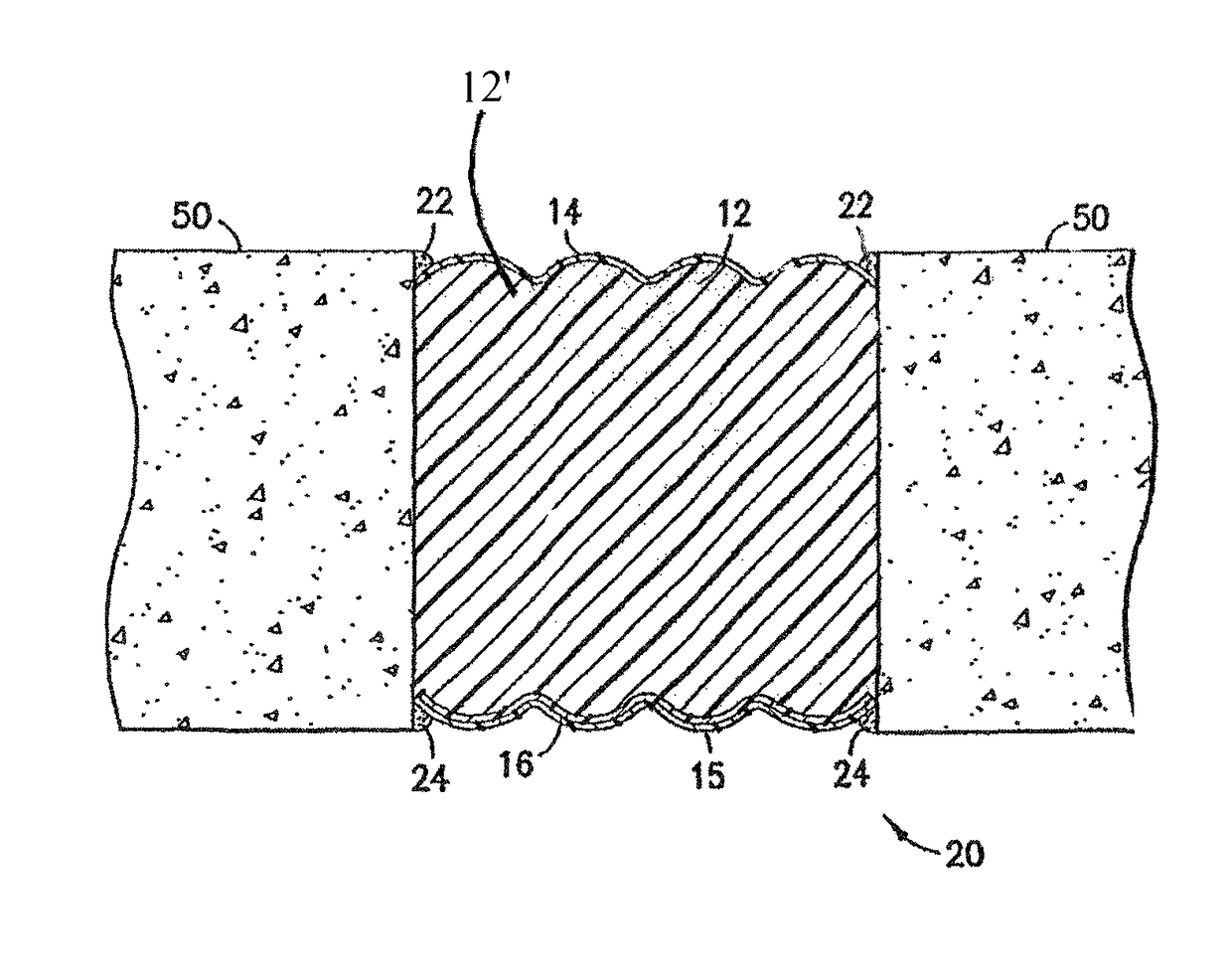
[0026]The expansion joint system described is best understood by referring to the attached drawings. The expansion joint system as described herein is shown as being installed between concrete substrates. The present invention is not limited in this regard, however, as the expansion joint system may be installed between substrates or surfaces other than concrete. Materials for such substrates or surfaces include, but are not limited to, glass, asphalt, stone (granite, marble, etc.), metal, and the like.

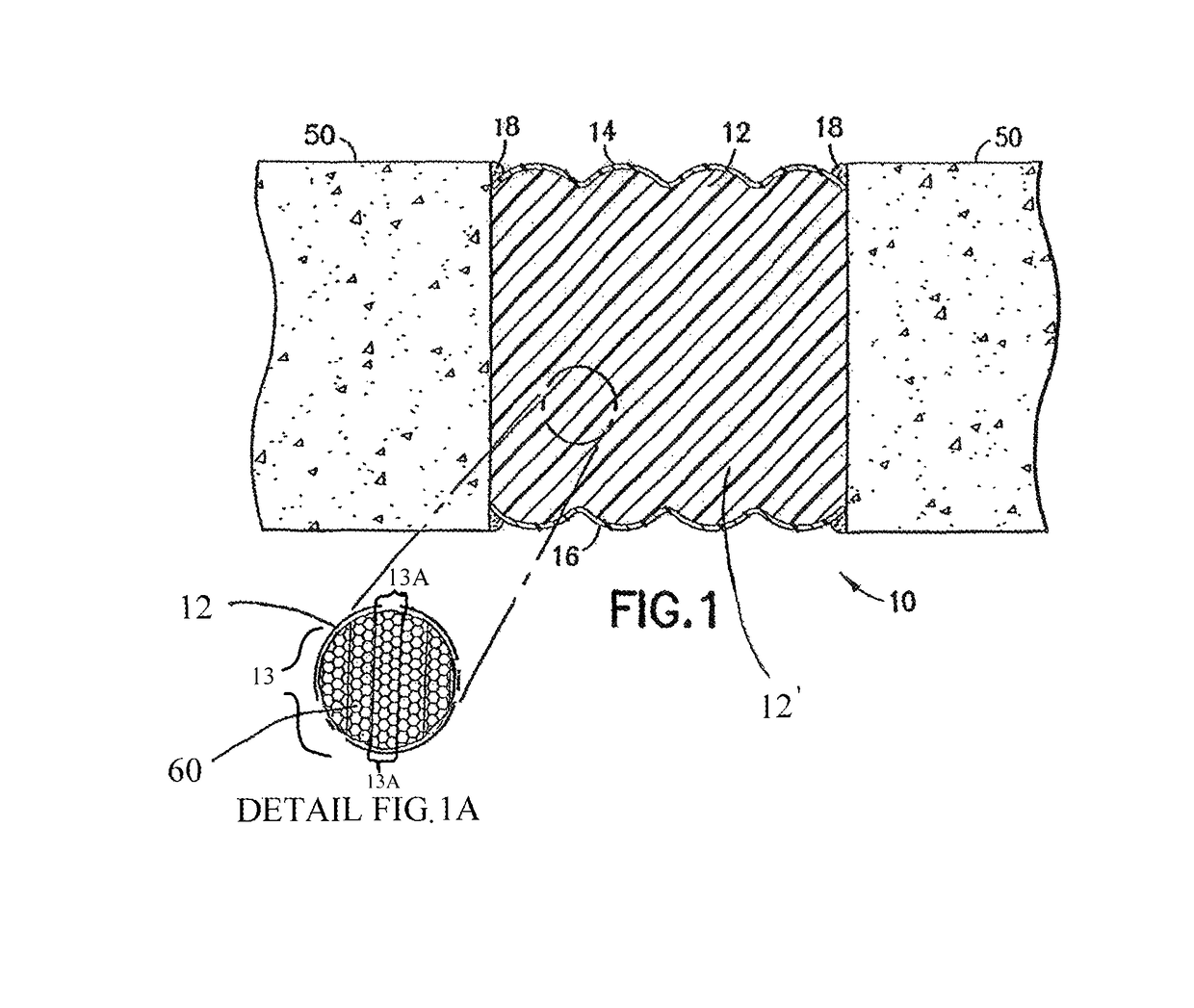
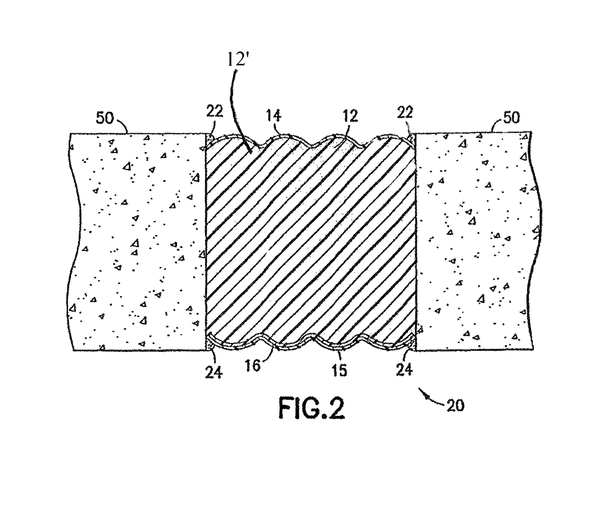
[0027]Referring to FIG. 1, one embodiment of an expansion joint system is shown at 10 and is hereinafter referred to as “system 10.” In system 10, a core 12′ comprising compressed laminations 13 of open celled polyurethane foam 12 (hereinafter referred to as “foam 12” for ease of reference which is not meant to limit the core 12′ to a foam material, but merely illustrate one exemplary material therefore) is infused with a fire retardant material 60 (as illustrated in Detail FIG. 1A) t...


PUM

PropertyMeasurementUnit
Temperatureaaaaaaaaaa

Abstract

A fire resistant and water resistant expansion joint system comprises a core; and a fire retardant infused into the core. The core infused with the fire retardant is configured to define a profile to facilitate compression of the fire and water resistant expansion joint when installed between substantially coplanar substrates.

Description

CROSS REFERENCE TO RELATED APPLICATION[0001]This application is a Continuation-in-Part Application of U.S. patent application Ser. No. 12 / 622,574, filed on Nov. 20, 2009, now U.S. Pat. No. 8,365,495, which claims the benefit of U.S. Provisional Patent Application No. 61 / 116,453, filed on Nov. 20, 2008, the contents of each of which are incorporated herein by reference in their entireties and the benefits of each are fully claimed herein.TECHNICAL FIELD[0002]The present invention relates generally to joint systems for use in architectural applications and, more particularly, to an expansion joint system for use in building and construction systems.BACKGROUND[0003]Building and construction applications in which materials such as concrete, metal, and glass are used typically employ joint systems that accommodate thermal and / or seismic movements of the various materials thereof and / or intentional movement of various elements relative to each other. These joint systems may be positioned ...

Claims


Application Information

Patent Timeline
IPC IPC(8): E04B1/68E04B1/94
CPCE04B1/948E04B1/6812E04B1/68E04B1/6806E04B1/944E04B1/98E04C2/205
Inventor WITHERSPOON, BILLHENSLEY, LESTER
Owner EMSEAL JOINT SYST
Why Eureka
Try Eureka